Inertial drive actuator
An inertial drive and actuator technology, applied in the direction of generator/motor, piezoelectric effect/electrostrictive or magnetostrictive motor, electrical components, etc., can solve the problem of lack of friction and long-term stability and other problems to achieve the effect of preventing circuit breakage, stabilizing driving, and reducing wear and tear
- Summary
- Abstract
- Description
- Claims
- Application Information
AI Technical Summary
Problems solved by technology
Method used
Image
Examples
no. 1 Embodiment approach )
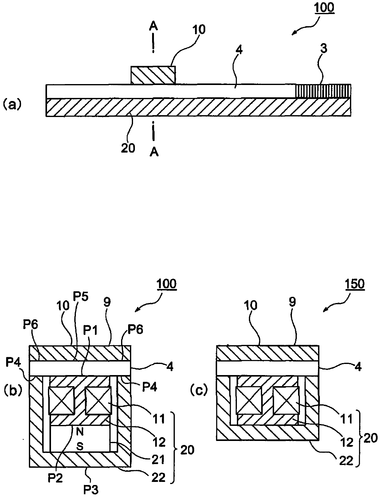
[0054] The inertial drive actuator of the first embodiment is shown in figure 1 . figure 1 (a) is the side view of the inertial drive actuator, figure 1 (b) is figure 1 Cross-sectional view at the position indicated by A-A in (a).
[0055] The inertial drive actuator 100 of the first embodiment is constituted by a piezoelectric element (displacement mechanism) 3 , a vibrating substrate 4 , a moving element 10 , and a stationary element 20 . The piezoelectric element 3 and the vibrating substrate 4 are located on the upper part of the fixed part 20 , and the moving part 10 is located on the upper part of the vibrating substrate 4 . The moving part 10 has the function of the first yoke 9 .
[0056] Both the piezoelectric element 3 and the vibrating substrate 4 are plate-shaped members. Here, a non-magnetic material is used for the vibrating substrate 4 . One end of the piezoelectric element 3 is mechanically connected to one end of the vibrating substrate 4 . In addit...
no. 2 Embodiment approach )
[0084] Next, an inertial drive actuator according to a second embodiment will be described.
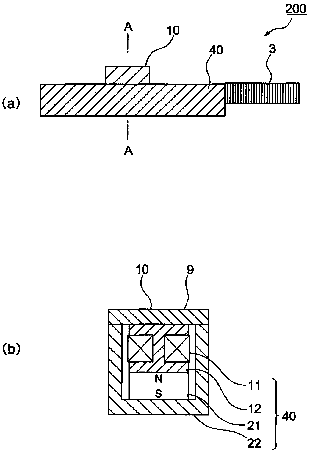
[0085] figure 2 (a) is a side view of the inertial drive actuator 200, figure 2 (b) is figure 2 Cross-sectional view at the position indicated by A-A in (a). The same reference numerals are assigned to the same configurations as those of the inertial drive actuator 100 of the first embodiment, and description thereof will be omitted.
[0086] The inertial drive actuator 200 of the second embodiment is constituted by the piezoelectric element 3 , the moving element 10 and the vibrating substrate 40 . The moving part 10 is located on the upper part of the vibrating substrate 40 . In addition, one end of the piezoelectric element 3 is mechanically connected to one end of the vibrating substrate 40 .
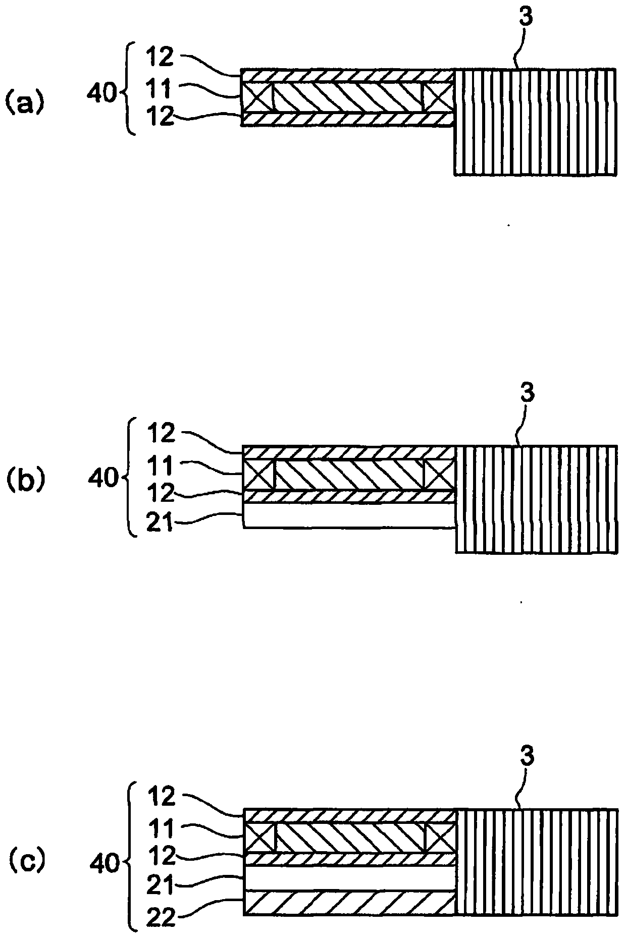
[0087] In addition, details of a configuration example in which the piezoelectric element 3 and the vibrating substrate 40 are connected will be described later.
[0088] The movin...
no. 3 Embodiment approach )
[0101] Next, an inertial drive actuator 300 according to a third embodiment will be described.
[0102] Figure 4 With figure 1 (b) Cross-sectional view of the same inertial drive actuator 300 . The same reference numerals are attached to the same components as those of the inertial drive actuator of the first embodiment, and description thereof will be omitted.
[0103] The inertial drive actuator 300 of the third embodiment is constituted by a piezoelectric element 3 (not shown), a vibrating substrate 4 , a moving element 10 , and a stationary element 20 . The piezoelectric element 3 and the vibrating substrate 4 are located on the upper part of the fixed part 20 , and the moving part 10 is located on the upper part of the vibrating substrate 4 .
[0104] The movable body 10 is composed of a first yoke 12d and a permanent magnet 13 . That is, the movable body 10 has a permanent magnet 13 .
[0105] On the other hand, the fixture 20 has the coil 11 and the second yokes ...
PUM
 Abstract
Description
Claims
Application Information
 - R&D
- Intellectual Property
- Life Sciences
- Materials
- Tech Scout
- Unparalleled Data Quality
- Higher Quality Content
- 60% Fewer Hallucinations
Browse by: Latest US Patents, China's latest patents, Technical Efficacy Thesaurus, Application Domain, Technology Topic, Popular Technical Reports.
© 2025 PatSnap. All rights reserved.Legal|Privacy policy|Modern Slavery Act Transparency Statement|Sitemap|About US| Contact US: help@patsnap.com


