Supercharge Your Innovation With Domain-Expert AI Agents!

Built-in axial flow roller driving device

A drive device, built-in technology, used in threshing equipment, applications, agricultural machinery and implements, etc., can solve the problems of troublesome maintenance and can only be installed at the rear of the axial flow drum.

Active Publication Date: 2014-06-25
郑宇虎 +1
View PDF5 Cites 1 Cited by
  • Summary
  • Abstract
  • Description
  • Claims
  • Application Information

AI Technical Summary

Problems solved by technology

However, for the vertical axial flow drum, especially when it is used together with the tangential flow drum, due to the limitation of structure and space, its driving device can only be installed at the rear of the axial flow drum. When the axial flow drum needs to be replaced or repaired , the driving device must be removed first, and then the axial flow roller can be removed, which is quite troublesome to overhaul

Method used


Image

  • Built-in axial flow roller driving device
  • Built-in axial flow roller driving device

Examples


Embodiment Construction

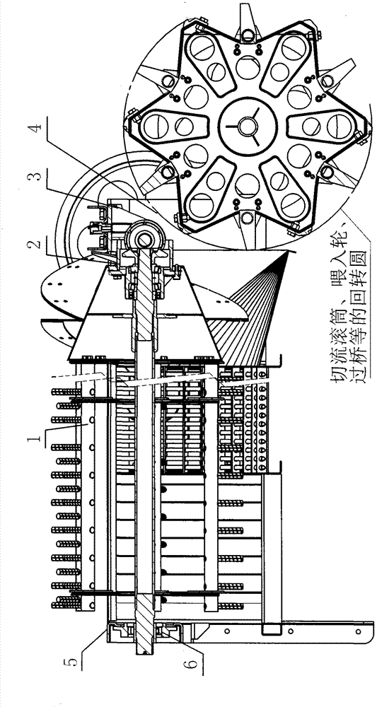
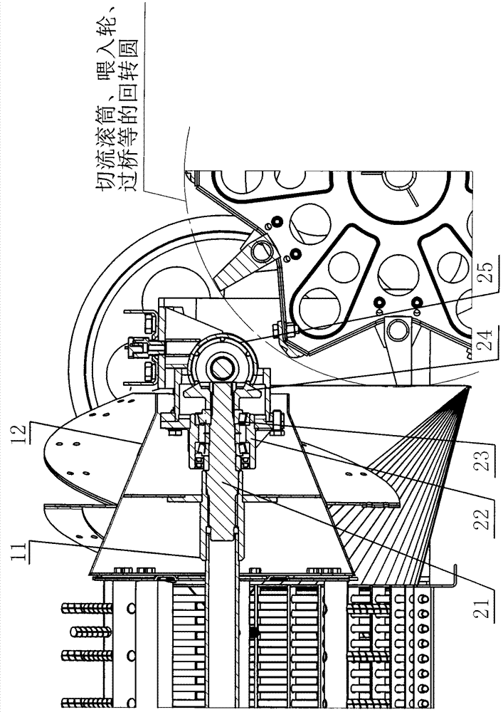
[0014] The present invention is a built-in axial flow roller driving device, which is mainly composed of an axial flow roller 1, a drive box 2, a front beam 3 and an axial flow frame 4, etc. The specific implementation method is as follows:

[0015] 1. The driving box 2 is hoisted on the front end of the axial flow frame 4 through the front beam 3. The front end of the central axis 11 of the axial flow drum 1 is indented into the leading cone 12 for a certain distance, leaving a cavity for the front end of the leading cone 12. When installing, the axial flow The front end of the central axis of the drum 1 is installed on the output shaft 21 of the driving box 2, and the power is supported and transmitted through the output shaft 21. At this time, the second half of the driving box 2 is just in the cavity of the leading cone 12 at the front end of the flow drum 1. The rear end of flow drum 1 is then supported by rear beam 5 and bearing 6 (see figure 1 and figure 2 ).

[0016...


PUM


Abstract

The invention relates to a built-in axial flow roller driving device. The built-in axial flow roller driving device is mainly composed of an axial flow roller, a driving box, a front cross beam, an axial flow frame and the like. The driving box is hung at the front end of the axial flow frame through the front cross beam, a part of the front end of a center shaft of the axial flow roller retracts into a guide-in cone, a section of cavity is reserved for the front end of the guide-in cone, the front end of the center shaft of the axial flow roller is installed on an output shaft of the driving box in the installing process, the output shaft is utilized to support the front end of the center shaft and transmit power, at the moment the rear half part of the driving box is just located in the cavity of the guide-in cone at the front end of the axial flow roller, and the rear end of the axial flow roller is supported by a rear cross beam and a bearing.

Description

technical field [0001] The invention relates to an axial-flow roller driving device, in particular to a built-in axial-flow roller driving device. Background technique [0002] Because the axial flow drum has many advantages such as high cleaning rate, strong separation ability, and wide application of crops, especially its simple structure, it can replace the complicated and huge key-type draft catcher on the combine harvester, so more and more combine harvesters are currently using it. machines are used. However, for the vertical axial flow drum, especially when it is used together with the tangential flow drum, due to the limitation of structure and space, its driving device can only be installed at the rear of the axial flow drum. When the axial flow drum needs to be replaced or repaired , the driving device must be removed first, and then the axial flow roller can be removed, which is quite troublesome to overhaul. Contents of the invention [0003] The purpose of t...

Claims


Application Information

Patent Timeline
Patent Type & Authority Applications(China)
IPC IPC(8): A01F12/56
Inventor 郑宇虎薛江涛
Owner 郑宇虎
Features
  • R&D
  • Intellectual Property
  • Life Sciences
  • Materials
  • Tech Scout
  • Unparalleled Data Quality
  • Higher Quality Content
  • 60% Fewer Hallucinations
Learn More