

Heat exchanger in vacuum solvent recovery device
A solvent recovery device and heat exchanger technology, applied in chemical instruments and methods, steam condensation, separation methods, etc., can solve problems such as poor cooling effect, achieve the effect of increasing retention and improving cooling efficiency
Inactive Publication Date: 2014-06-25
JIANGSU FEIYA CHEM IND
View PDF5 Cites 0 Cited by
- Summary
- Abstract
- Description
- Claims
- Application Information
AI Technical Summary
Problems solved by technology
[0002] In the heat exchanger in the vacuum solvent recovery device in the prior art, the medium leaks from the bottom of the condenser partition, and directly returns to the water tank through the condenser, so the cooling effect is poor
Method used
View moreImage
Smart ImageViewing Examples

Examples
Embodiment Construction
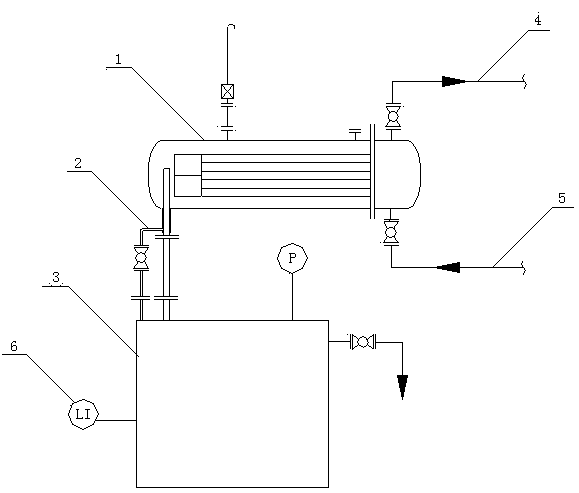
[0010] Such as figure 1 The shown heat exchanger in a vacuum solvent recovery device includes a working fluid condenser 1, a pipeline 2 and a working fluid buffer tank 3, the bottom of the working fluid condenser 1 is provided with a pipeline 2, and a part of one end of the pipeline 2 extends into the In the working fluid condenser 1, the other end of the pipeline 2 is connected with a working fluid buffer tank 3, the working fluid condenser 1 is provided with a cooling water inlet 5 and a cooling water outlet 6, and the working fluid buffer tank 3 is provided with a liquid level 6, the length of the pipeline 2 extending into the working fluid condenser 1 is greater than half of the height of the working fluid condenser 1.
Login to View More PUM
 Abstract
The invention discloses a heat exchanger in a vacuum solvent recovery device. The heat exchanger in the vacuum solvent recovery device comprises a working solution condenser, a pipeline and a working solution buffer tank, wherein the pipeline is arranged at the bottom of the working solution condenser; one part of one end of the pipeline extends inside the working solution condenser; the other end of the pipeline is connected with the working solution buffer tank; and a cooling water inlet and a cooling water outlet are formed in the working solution condenser. By improving the liquid return interface of the condenser, the retention volume of a medium in the condenser is increased, and the cooling efficiency is improved.
Description
technical field [0001] The invention relates to a heat exchanger, in particular to a heat exchanger in a vacuum solvent recovery device. Background technique [0002] In the heat exchanger in the vacuum solvent recovery device in the prior art, the medium leaks liquid from the bottom of the condenser partition, and directly returns the liquid to the water tank through the condenser, so the cooling effect is poor. Contents of the invention [0003] Purpose of the invention: The purpose of the invention is to provide a heat exchanger in a vacuum solvent recovery device with high heat exchange efficiency in order to solve the deficiencies in the prior art. [0004] Technical solution: The heat exchanger in a vacuum solvent recovery device according to the present invention includes a working fluid condenser, a pipeline and a working fluid buffer tank, the bottom of the working fluid condenser is provided with a pipeline, and one end of the pipeline is A part extends into...
Claims
Login to View More Application Information
Patent Timeline
 IPC IPC(8): B01D5/00
CPCY02P70/10
Inventor 曹宏生王宇夏正张海峰
Owner JIANGSU FEIYA CHEM IND