Switching device and method of opening the switching device

A switch device and key technology, applied in building locks, buildings, building structures, etc., can solve problems such as hidden safety hazards

Inactive Publication Date: 2014-06-25
HONG FU JIN PRECISION IND (SHENZHEN) CO LTD +1
View PDF3 Cites 4 Cited by
  • Summary
  • Abstract
  • Description
  • Claims
  • Application Information

AI Technical Summary

Problems solved by technology

[0003] However, since conventional locks have an open keyhole, they can only be locked against by untrained persons.
For professionals or trained personnel, you can use a flashlight to illuminate the internal groove, copy the key according to the shape of the groove, or even use a wire to open the door lock, resulting in a greater safety hazard

Method used


Image

  • Switching device and method of opening the switching device
  • Switching device and method of opening the switching device

Examples


Embodiment Construction

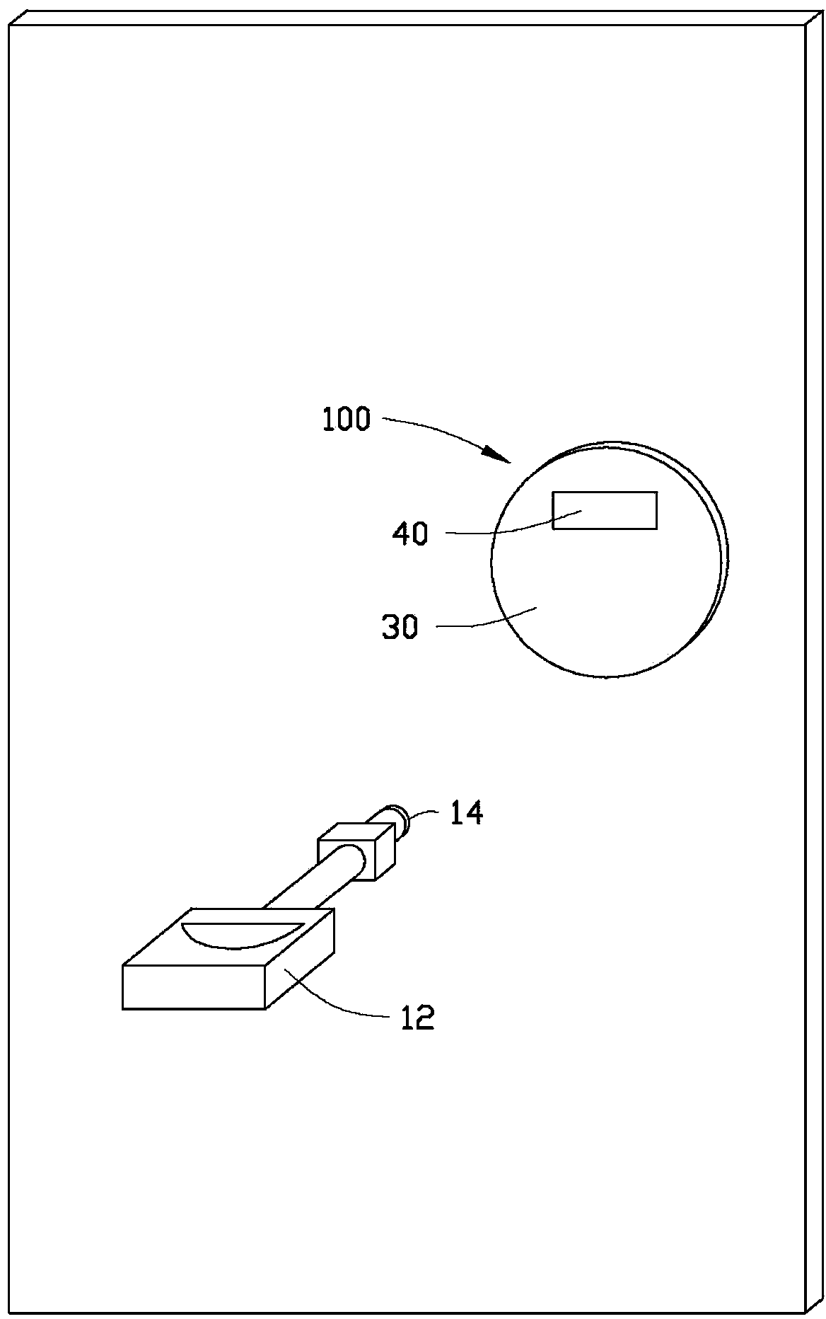
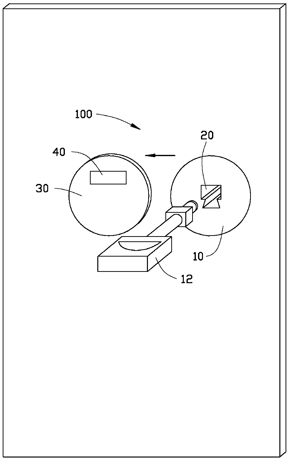
[0017] see figure 1 and figure 2 , a switch device 100 provided by an embodiment of the present invention includes a lock 10 and a key 12 for unlocking. The lock 10 is provided with a lock hole 20 , the key 12 is inserted into the lock hole 20 and rotated at a predetermined angle to open the lock 10 of the switch device 100 . In this embodiment, the lock 10 is a door lock.

[0018] A signal transmitter 14 is installed on the top of the key 12. In this embodiment, the signal transmitter 14 is a light source, and the light source is a light emitting diode. The luminescent light source can emit a light signal, the light signal is a pulse signal, and the combination of at least two of pulse width, pulse interval and pulse frequency is used to represent the unlocking signal. The key 12 also includes a controller (not shown in the figure) to control the light source to send out the pulsed light signal.

[0019] A shielding part 30 is installed outside the lockhole 20. When the ...


PUM


Abstract

A switching device comprises a lock and a key. The lock is provided with a lock hole. The switching device further comprises a shield part which shields the lock hole. The key is provided with a signal transmitter. The shelter part is provided with a signal receiver. When an unlock signal transmitted by the signal transmitter of the key is received by the signal receiver, the shield part moves to expose the lock hole so that the key can be inserted in. The invention further relates to a method of opening the switching device.

Description

technical field [0001] The invention relates to a switch device, in particular to a switch device using a light-sensing control mechanism and a method for opening the switch device. Background technique [0002] Door is indispensable for every household, and switch device is assembled on the door, as door lock, is to prevent outsiders from entering the room at will. Traditional mechanical locks are provided with a keyhole, and the lock can be opened and the door opened by turning the key after the key is inserted. [0003] However, since conventional locks have an open keyhole, they can only be secured by untrained persons. For professionals or trained personnel, you can use a flashlight to illuminate the groove inside, copy the key according to the shape of the groove, or even use a wire to open the door lock, resulting in a greater safety hazard. Contents of the invention [0004] In view of this, it is necessary to provide an anti-theft switch device. [0005] A swit...

Claims


Application Information

Patent Timeline
Patent Type & Authority Applications(China)
IPC IPC(8): E05B17/14
Inventor 许义忠
Owner HONG FU JIN PRECISION IND (SHENZHEN) CO LTD
Why Eureka
Try Eureka