Oil pumping device indicator diagram dynamic identification method and device based on BP neural network

A BP neural network and oil pumping equipment technology, applied in the field of equipment management, to achieve the effect of enhancing the degree of automation management, improving the management system, and improving work efficiency

Inactive Publication Date: 2014-06-25
洛阳乾禾仪器有限公司
View PDF3 Cites 8 Cited by
  • Summary
  • Abstract
  • Description
  • Claims
  • Application Information

AI Technical Summary

Benefits of technology

This technology helps manage pumps during drilling or other activities without manually checking them visually. It involves training an artificial intelligence (AIN) model with data from different types of indicators on specific parts of the machine's surface called bipolar plates. By learning these patterns over time, ANN models are able to recognize new signs indicating how much fluid they have been injected into each section of pipe underground. These systems help operators efficiently plan future maintenance tasks while also ensuring better quality control measures such as water injection rates. Overall, this technology makes it easier and more efficient than manual inspections.

Problems solved by technology

This patented technical problem addressed by the patents relating to managing oil pumps during drilling operations involves automatically analyzing indicators from the machine's performance logs without requiring human interventions or relying solely upon data provided by sensors.

Method used


Image

  • Oil pumping device indicator diagram dynamic identification method and device based on BP neural network
  • Oil pumping device indicator diagram dynamic identification method and device based on BP neural network
  • Oil pumping device indicator diagram dynamic identification method and device based on BP neural network

Examples


Embodiment 1

[0026] Embodiment 1. A method for dynamically identifying the dynamometer diagram of the oil pumping equipment based on the BP neural network.

[0027] The method of this embodiment mainly includes two parts, one part is: the establishment process of the feature library, and the other part is the process of dynamically identifying the collected oil pumping equipment indicator diagram by using the successfully established feature library. Combine below Figure 1-9 The contents of these two parts are explained separately.

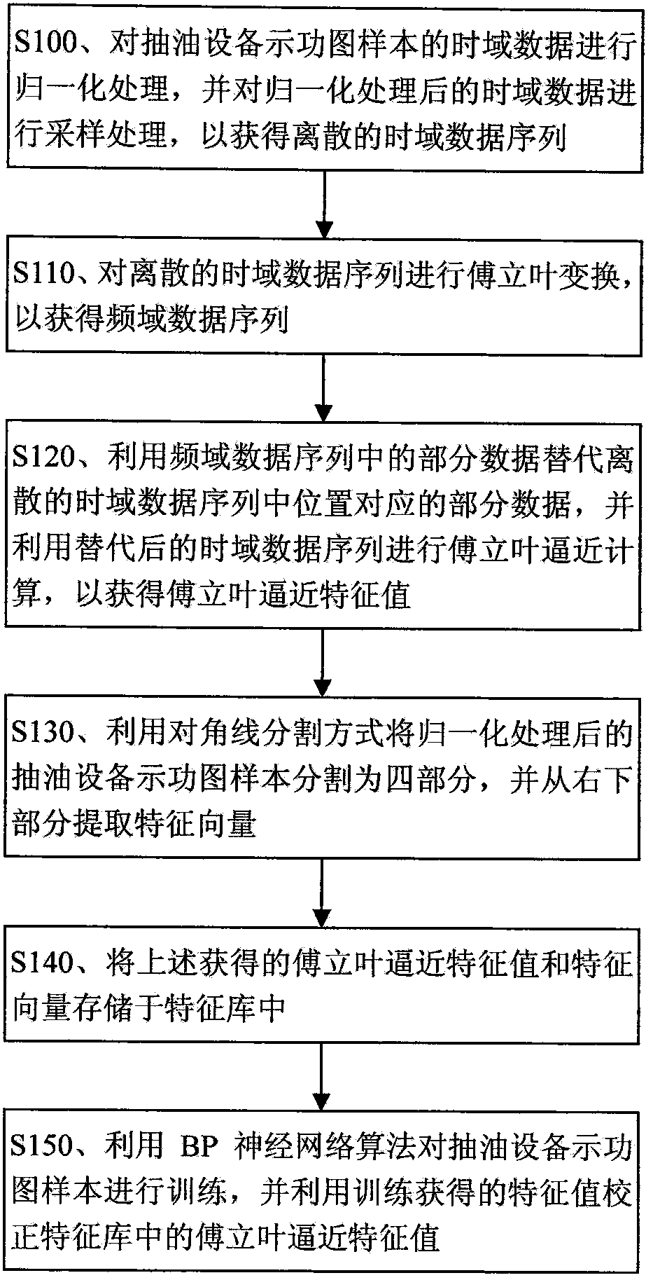
[0028] 1. The establishment process of the feature library, the process is as follows figure 1 shown.

[0029] figure 1 In S100 , firstly perform normalization processing on the time-domain data of the dynamometer sample of the oil pumping equipment, and then perform sampling processing on the normalized time-domain data, so as to obtain a discrete time-domain data sequence.

[0030] The sample of the dynamometer diagram of the above-mentioned oil pumping...

Embodiment 2

[0120] Embodiment 2: A device for dynamically identifying the dynamometer diagram of the oil pumping equipment based on the BP neural network.

[0121] The device of this embodiment mainly includes: an establishment module and an identification module.

[0122] The build module is mainly used to build a feature library. The created feature library can be stored in the building module or in other storage modules.

[0123] The identification module is mainly used to dynamically identify the received oil pumping equipment indicator diagrams by using the feature library successfully established by the above-mentioned establishment module after receiving the collected oil pumping equipment indicator diagrams transmitted from the outside.

[0124] The above-mentioned establishment modules mainly include: a normalization module, a Fourier transform module, a Fourier approximation module, an extraction module, a feature library and a training module. The identification module above ...


PUM


Abstract

The invention relates to an oil pumping device indicator diagram dynamic identification method and device based on a BP neural network. The method comprises the steps of characteristic database establishing and dynamic identification. An establishing process comprises the steps that time domain data of an oil pumping device indicator diagram sample are normalized and sampled to acquire a discrete time domain data sequence; Fourier transformation is carried out on the time domain data sequence to acquire a frequency domain data sequence; partial data in the frequency domain data sequence are used to replace partial data in the time domain data sequence, and a Fourier approximation characteristic value is acquired; the normalized oil pumping device indicator diagram sample is divided into four parts, and a characteristic vector is extracted; the Fourier approximation characteristic value and the characteristic vector are stored in a characteristic database; and a BP neural network algorithm is used to train the oil pumping device indicator diagram sample, so as to correct the Fourier approximation characteristic value in the database. According to the invention, the automation management level of an oil pumping device is enhanced; the work efficiency in an oil field is improved; and the management system of oil well operation is improved.

Description


Claims


Application Information

Patent Timeline
Owner 洛阳乾禾仪器有限公司
Why Eureka
Try Eureka