A data transmission method for a filter bank multi-carrier system
A data transmission method and technology of multi-carrier system, applied in multi-carrier system, baseband system components, shaping network in transmitter/receiver, etc., can solve the problem of FBMC system pilot frequency imaginary part interference and other issues
- Summary
- Abstract
- Description
- Claims
- Application Information
AI Technical Summary
Problems solved by technology
Method used
Image
Examples
Embodiment 1
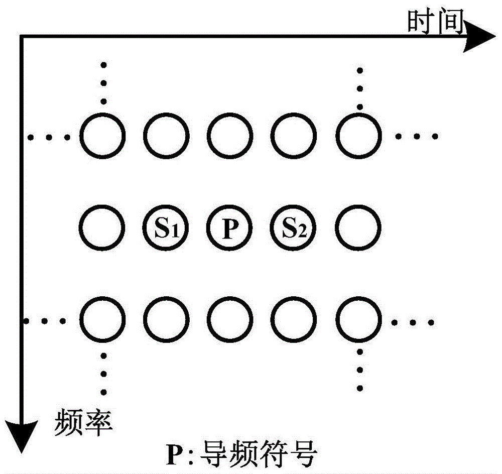
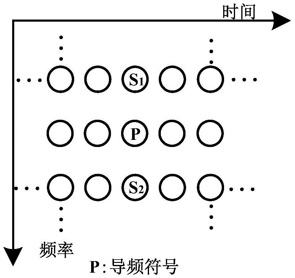
[0016] Embodiments of the present invention include the step of calculating the imaginary part interference suffered by the pilot, and designing adjacent symbols S of the pilot 1 and S 2 , sending and receiving data step, channel estimation and equalization step, data recovery step, is characterized in that:
[0017] (1) Steps for calculating the imaginary part interference received by the pilot: two adjacent symbols with the same frequency as the pilot symbol are respectively denoted as S 1 and S 2 , the other m symbols around the pilot symbol are denoted as D=[d 1 , d 2 , d 3 ,... d m ] T , the interference coefficient of each data to the pilot symbol is known, denoted as A=[a 1 ,a 2 ,a 3 ,...,a m ], so the imaginary interference from the data symbol D to the pilot is I=AD.
[0018] (2) Design the adjacent symbol S of the pilot 1 and S 2 Step: record the extra data to be sent as x, according to (where b 1 for S 1 Interference coefficient to pilot, b 2 for S...
Embodiment 2
[0028] Another embodiment of the present invention includes the step of calculating the imaginary part interference suffered by the pilot, and designing adjacent symbols S of the pilot 1 and S 2 Step, sending and receiving data step, channel estimation and equalization step, data restoration step, is characterized in that:
[0029] (1) Calculating the imaginary part interference step of the pilot: two adjacent symbols at the same time as the pilot symbol are respectively denoted as S 1 and S 2 , the other m symbols around the pilot symbol are denoted as D=[d 1 , d 2 , d 3 ,... d m ] T , the interference coefficient of each data to the pilot symbol is known, denoted as A=[a 1 ,a 2 ,a 3 ,...,a m ], so the imaginary interference from the data symbol D to the pilot is I=AD.
[0030] (2) Design the adjacent symbol S of the pilot 1 and S 2 Step: record the extra data to be sent as x, according to (where b 1 for S 1 Interference coefficient to pilot, b 2 for S 2 In...
Embodiment 3
[0040] This specific embodiment is a FBMC system with 256 subcarriers, wherein the symbol mapping method adopts the BPSK mapping method, that is, bit 0 is mapped to symbol +1, bit 1 is mapped to symbol -1, and each carrier sends 20 symbols. The filter used is a Phydas filter.
[0041] (1) Steps to calculate the imaginary part interference received by the pilot: assuming S 1 and S 2 It is necessary to cancel the imaginary part interference of the data in the surrounding 3×7 area to the pilot symbol, and remove 1 pilot symbol and S in the 3×7 area 1 , S 2 , a total of 18 data, recorded as D=[d 1 , d 2 , d 3 ,... d 18 ] T , the interference coefficient of each data to the pilot symbol is known, denoted as A=[a 1 ,a 2 ,a 3 ,...,a 18 ], so the imaginary interference from the data symbol D to the pilot is I=AD.
[0042] (2) Design the adjacent symbol S of the pilot 1 and S 2 Step: due to the adoption of BPSK mapping, assuming that the extra data to be sent is x=1, then...
PUM
 Abstract
Description
Claims
Application Information
 - R&D
- Intellectual Property
- Life Sciences
- Materials
- Tech Scout
- Unparalleled Data Quality
- Higher Quality Content
- 60% Fewer Hallucinations
Browse by: Latest US Patents, China's latest patents, Technical Efficacy Thesaurus, Application Domain, Technology Topic, Popular Technical Reports.
© 2025 PatSnap. All rights reserved.Legal|Privacy policy|Modern Slavery Act Transparency Statement|Sitemap|About US| Contact US: help@patsnap.com


