Electric reciprocating saw

A reciprocating saw, electric technology, applied in the direction of motorized reciprocating cross-cutting saw, circular saw, sawing equipment, etc., can solve the problems of reduced cutting efficiency, large machine vibration, troublesome operation, etc., to achieve the effect of easy cutting and simple structure

Active Publication Date: 2014-07-02
POSITEC POWER TOOLS (SUZHOU) CO LTD
View PDF12 Cites 6 Cited by
  • Summary
  • Abstract
  • Description
  • Claims
  • Application Information

AI Technical Summary

Problems solved by technology

[0002] When the electric reciprocating saw cuts branches or round wood, the workpiece will be pushed forward due to the reciprocating motion of the saw blade, which will cause the machine itself to vibrate greatly, and due to The movement of the workpiece is in the same direction as that of the saw blade, and the cutting efficiency will decrease
The existing electric reciprocating saw includes a base frame, a power drive mechanism arranged on the base frame, and a saw blade driven by the power drive mechanism. The front part of the base frame has a stopper, and the The saw blade extends forward in a linear shape from the stopper, the base frame is provided with a positioning clip, the positioning clip is slidably arranged on the base frame, and a locking mechanism is provided between the two, Therefore, when continuously cutting wood of different sizes, it is necessary to unlock the locking mechanism and manually adjust the position of the positioning clip so that it can clamp the corresponding wood, and the lock is troublesome to operate, and the small parts of the locking mechanism are easy to lose

Method used


Image

  • Electric reciprocating saw
  • Electric reciprocating saw
  • Electric reciprocating saw

Examples


Embodiment Construction

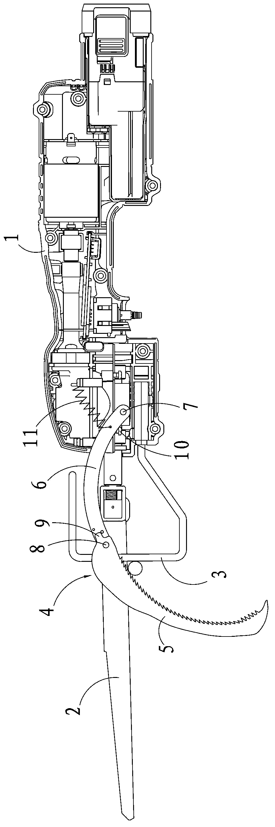
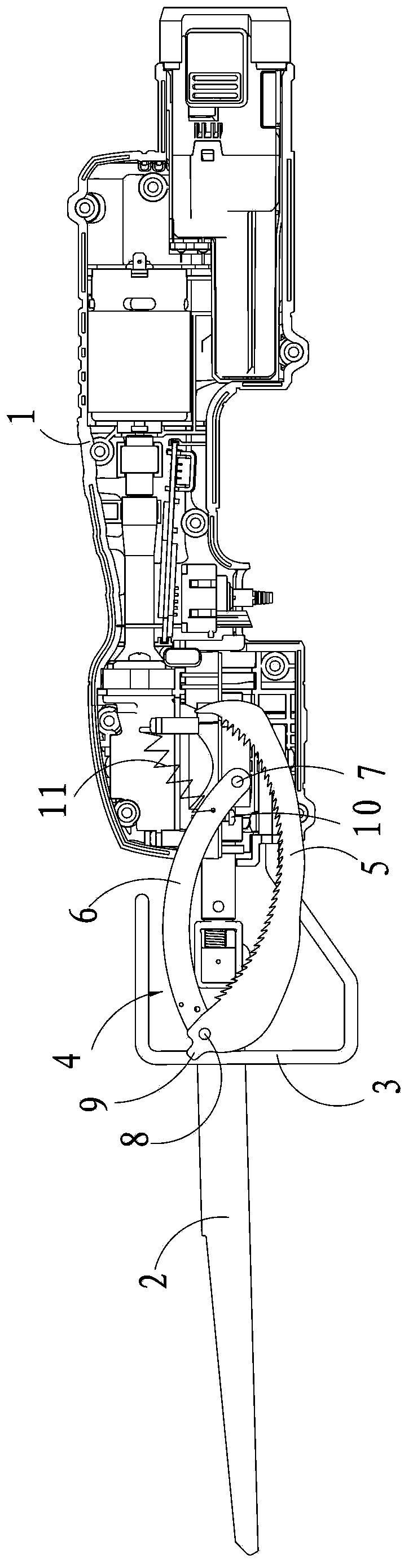
[0020] As shown in the drawings, an electric reciprocating saw includes a base frame 1, a power driving mechanism arranged on the base frame 1, and a saw blade 2 driven by the power driving mechanism. The power drive mechanism includes motors, controllers, etc.

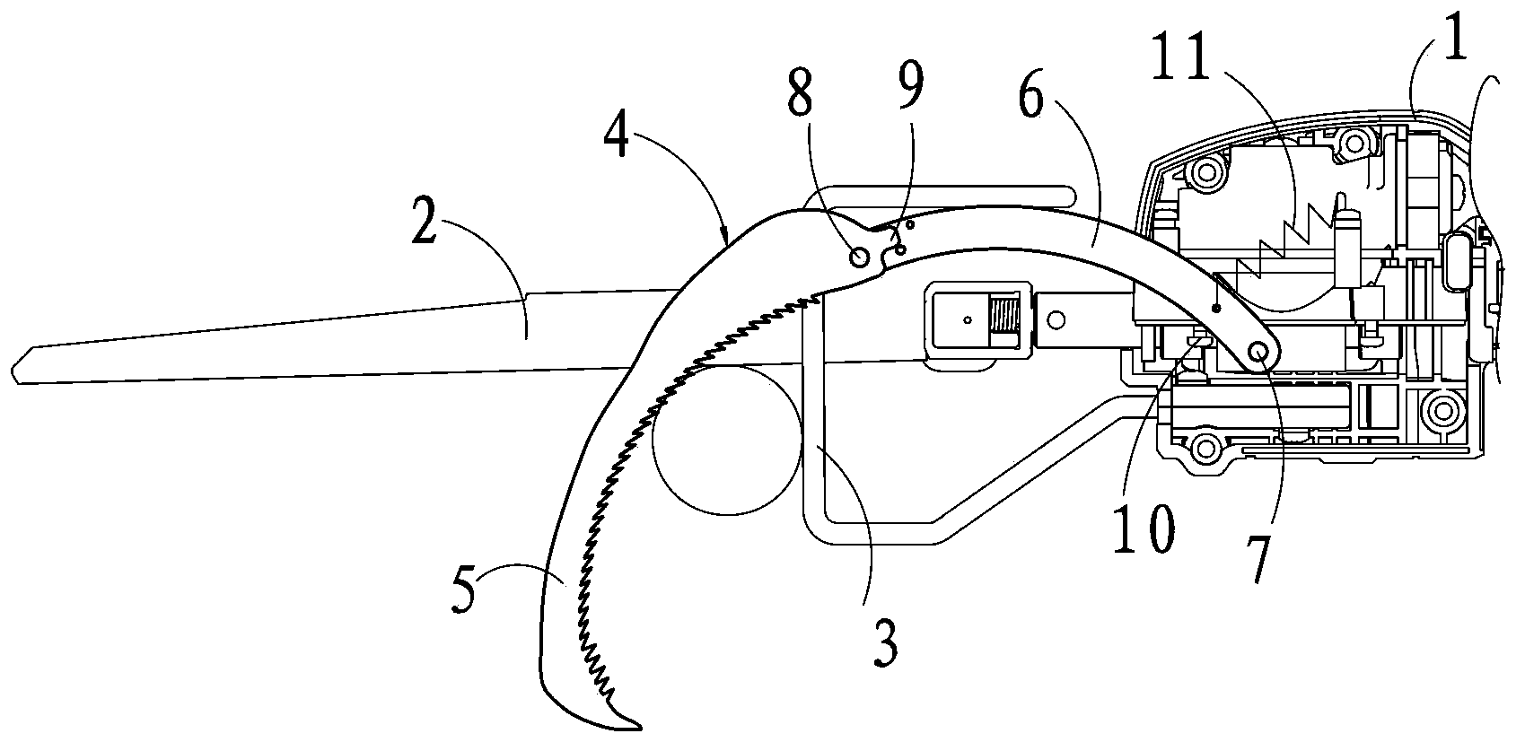
[0021] The front part of the base frame 1 has a stopper 3, and the saw blade 2 extends forward in a linear form from the stopper 3. When in use, the saw blade 2 performs reciprocating cutting motions back and forth.

[0022] The base frame 1 is provided with a positioning clip 4, the positioning clip 4 is connected with the base frame 1 in a rotational manner around the first axis 7, the positioning clip 4 includes a positioning clip body 5, and the positioning clip body 5 is used to conflict with the wood to be cut. The side edge is an arc-shaped edge that is concave inward, and there are multiple teeth on the arc-shaped edge that are used to interfere with the wood to be cut. When the positioning clip 4 is used, a g...


PUM


Abstract

An electric reciprocating saw comprises a base frame, a power driving mechanism and a saw blade, wherein the power driving mechanism is arranged on the base frame, and the saw blade is driven by the power driving mechanism. A stopper is arranged in the front of the base frame, the saw blade linearly extends forwards from the stopper, a positioning clamp is arranged on the base frame, the positioning clamp is connected with the base frame by rotating around a first rotating shaft, the positioning clamp comprises a positioning clamp body, one side edge, used for abutting against wood to be cut, of the positioning clamp body is in an arc concaved inwardly, and the arc edge is provided with a plurality of teeth used for abutting against the wood to be cut. When the positioning clamp is in use, a clamping space capable of containing the wood to be cut can be formed between the positioning clamp body and the stopper; when cut by the electric reciprocating saw, the wood can be clamped between the stopper and the positioning clamp body, and friction is generated between the teeth on the positioning clamp and the wood, so that the wood is stably clamped between the stopper and the positioning clamp body, cutting is convenient to finish, and the structure is simple.

Description

technical field [0001] The invention relates to an electric reciprocating saw for cutting trees or wood. Background technique [0002] When the electric reciprocating saw cuts branches or round wood, the reciprocating motion of the saw blade will push the workpiece forward, which will cause the machine itself to vibrate greatly, and because the movement of the workpiece is in the same direction as the saw blade, the cutting efficiency will decrease. The existing electric reciprocating saw includes a base frame, a power drive mechanism arranged on the base frame, and a saw blade driven by the power drive mechanism. The front part of the base frame has a stopper, and the The saw blade extends forward in a linear shape from the stopper, the base frame is provided with a positioning clip, the positioning clip is slidably arranged on the base frame, and a locking mechanism is provided between the two, Therefore, when continuously cutting wood of different sizes, it is necessary ...

Claims


Application Information

Patent Timeline
Patent Type & Authority Applications(China)
IPC IPC(8): B27B11/10
CPCB23D49/16B23D49/002B23D51/04
Inventor 霍立祥张士松
Owner POSITEC POWER TOOLS (SUZHOU) CO LTD
Why Eureka
Try Eureka