Supercharge Your Innovation With Domain-Expert AI Agents!

Teeth for disperser plate having grooves and taper

A technology of dispersing machine and machine disc, applied in paper machine, wet end of paper machine, textile and paper making, etc., can solve problems such as limitations

Inactive Publication Date: 2014-07-02
ANDRITZ AG
View PDF1 Cites 0 Cited by
  • Summary
  • Abstract
  • Description
  • Claims
  • Application Information

AI Technical Summary

Problems solved by technology

Adding more teeth generally increases the efficiency of the dispersion process, but the size of the teeth that can be manufactured at reasonable cost limits this number

Method used


Image

  • Teeth for disperser plate having grooves and taper
  • Teeth for disperser plate having grooves and taper
  • Teeth for disperser plate having grooves and taper

Examples


Embodiment Construction

[0036]Increasing the number of contact edges for the material can improve the breakdown of dirt and stickies in the fiber stock and increase the efficiency of the disperser.

[0037] A disperser disk segment according to any of the embodiments of the present disclosure has at least one tooth, the inner or outer frontal surface of the tooth comprising at least two grooves. Any combination of groove length, width, shape, grooves of decreasing width, grooves of decreasing depth, or angled grooves on the inner or outer frontal surface of teeth with at least two grooves can be used.

[0038] Although the grooves are depicted as oblong, cylindrical or conical in the drawings, the grooves may be triangular, pyramidal or quadrangular in other embodiments.

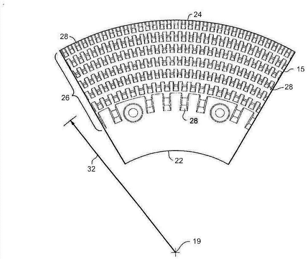
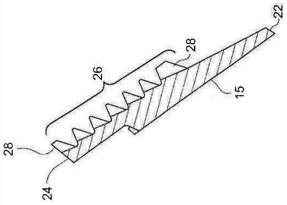
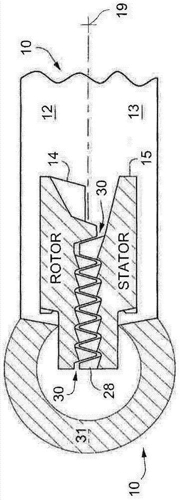
[0039] Figures 1a, 1b and 1c show a conventional disk section 10 of a disperser. In FIG. 1 a, the conventional disk segment 10 is a turntable disk segment 15 . Each conventional disc segment 10 is a die-cast metal piece in the sh...


PUM

PropertyMeasurementUnit
angleaaaaaaaaaa

Abstract

A disperser plate segment for removing contaminants from fiber stock, the segment comprising: radially inner and outer edges, multiple radially concentric rows of teeth, each row of teeth having multiple teeth defining multiple channels disposed intermediate the teeth, each of the channels having a lower channel base surface and each of the teeth having a top surface, at least one face surface extending from the channel base surface to the top surface, and wherein at least one of the face surfaces comprises at least two grooves.

Description

[0001] related application [0002] This application claims priority to US Provisional Patent Application No. 61 / 746,011, filed December 26, 2012, which is hereby incorporated by reference in its entirety. technical field [0003] The present disclosure relates to disperser disk segments. Background technique [0004] Recycled paper and packaging materials are referred to as "fiber stock" by those skilled in the art. Fiber stock usually goes through several processes to remove ink and toner from copy paper. Soils such as plastic are collectively referred to as "stickies" by those in the art. The removal process is not entirely effective, and residual ink, toner and stickies are typically dispersed to avoid stickies from sticking to paper machine parts and causing holes or weak spots in the new paper. Stickies clumping and building up on the paper machine cause idle time, which increases the cost of the manufacturing process. Residual ink particles typically show up as gl...

Claims


Application Information

Patent Timeline
Patent Type & Authority Applications(China)
IPC IPC(8): D21C9/08
CPCB02C7/12D21D1/008D21F1/0018D21D5/00
Inventor 伊斯莫·伊哈莱恩
Owner ANDRITZ AG
Features
  • R&D
  • Intellectual Property
  • Life Sciences
  • Materials
  • Tech Scout
  • Unparalleled Data Quality
  • Higher Quality Content
  • 60% Fewer Hallucinations
Learn More