
Motor spindle capable of dissipating heat

A technology for motors and heat sinks, applied in the field of motor spindles, can solve problems such as component fatigue, rotor 3 and spindle 4 cannot be quickly dissipated, reduce motor performance and life, and achieve the effect of increasing gas flow

Active Publication Date: 2014-07-02
永元电机(苏州)有限公司
View PDF8 Cites 1 Cited by
  • Summary
  • Abstract
  • Description
  • Claims
  • Application Information

AI Technical Summary

Problems solved by technology

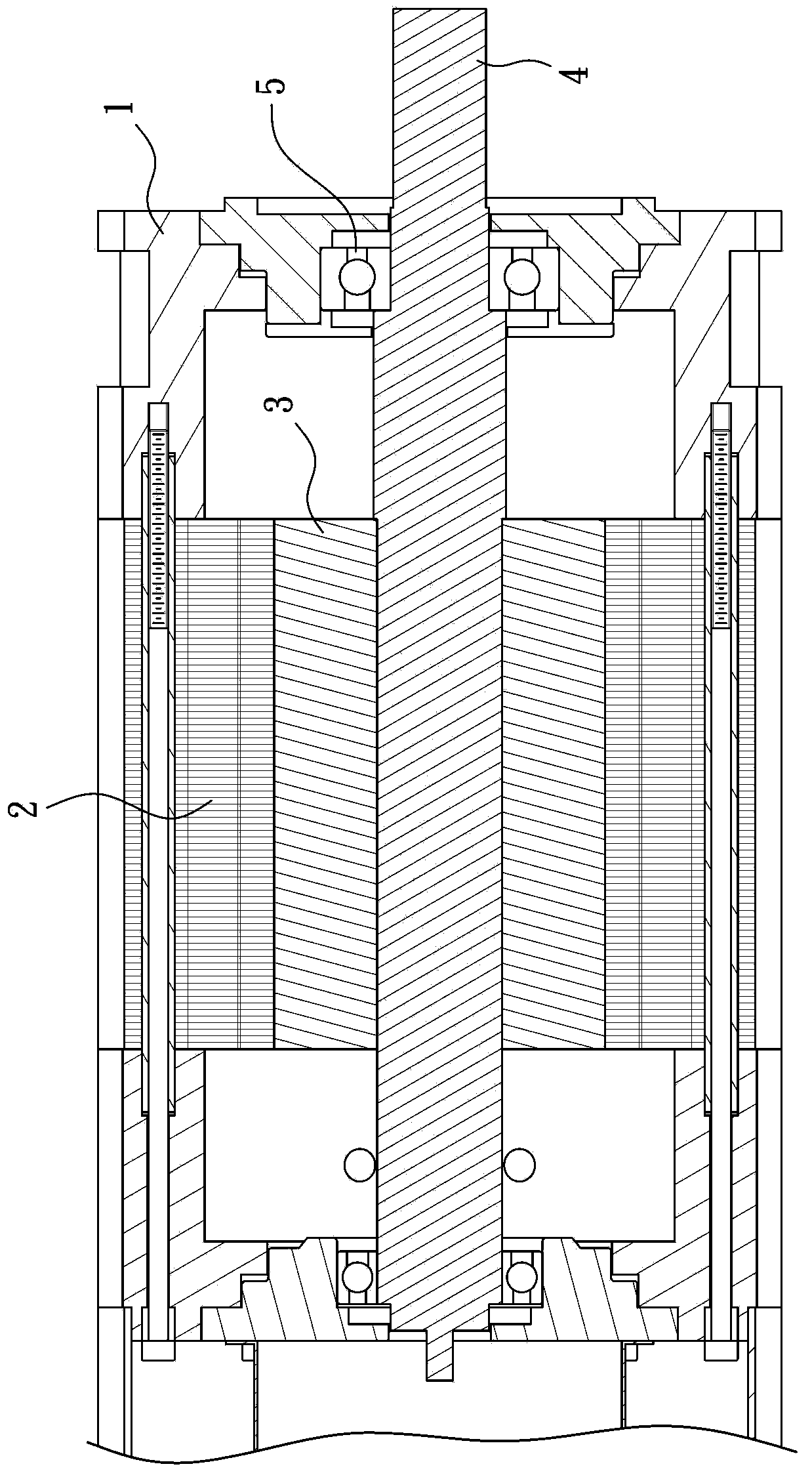
[0003] The change of the magnetic field generated by the internal coil of the stator 2 interacts with the magnetic field of the rotor 3, and then drives the rotor 3 to rotate together with the spindle 4. Due to the high-speed rotation, the temperature of the rotor 1 and the spindle 4 will increase. , and the excessively high temperature is likely to cause the fatigue of components, and the accumulated heat energy cannot be dissipated quickly for the rotor 3 and the spindle 4, thereby reducing the service performance and life of the motor. According to the above-mentioned deficiency, the conventional motor is still has room for improvement

Method used


Image

  • Motor spindle capable of dissipating heat
  • Motor spindle capable of dissipating heat
  • Motor spindle capable of dissipating heat

Examples


Embodiment Construction

[0026] In order to illustrate the central idea of ​​the present invention expressed in the column of the above-mentioned summary of the invention, it is expressed in specific embodiments. Various objects in the embodiments are drawn according to the scale suitable for illustration and description, rather than according to the scale of the actual components, and are described first.

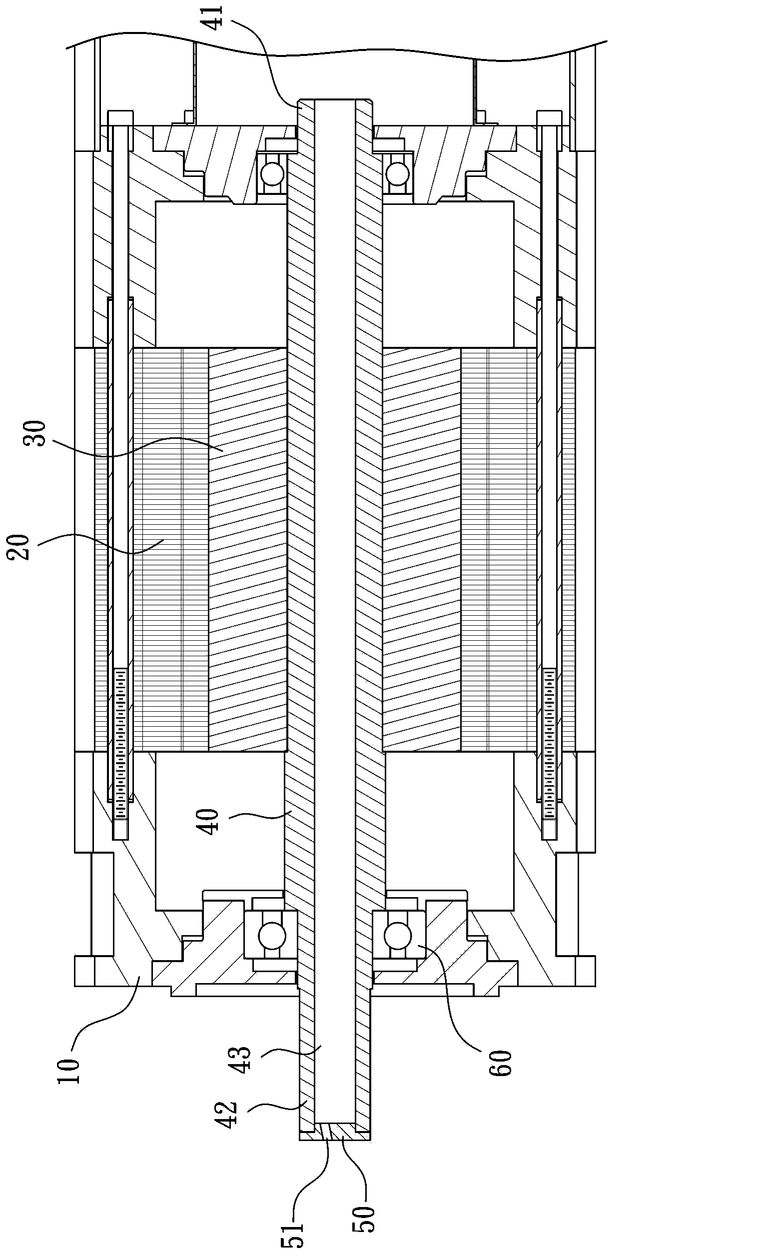
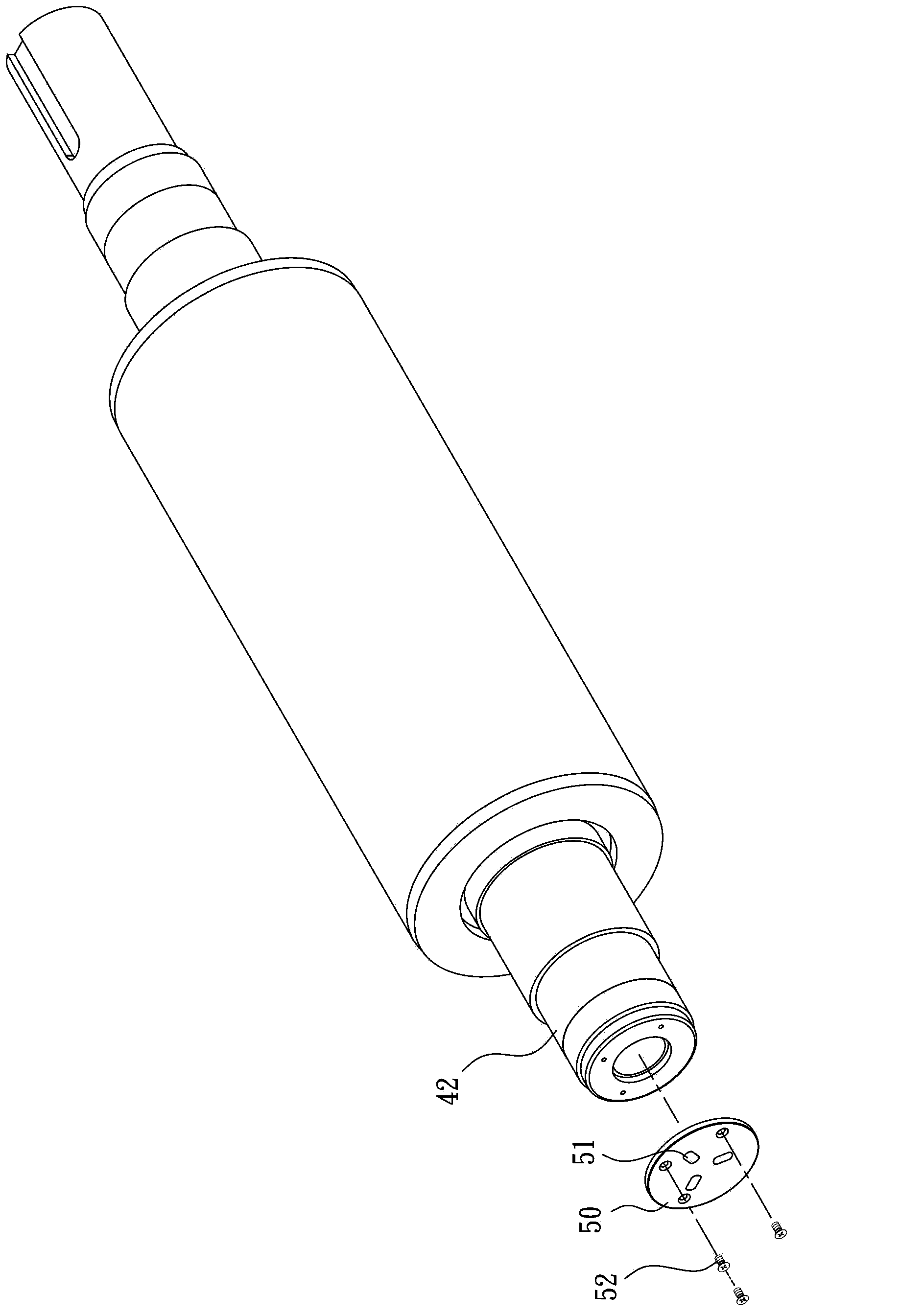
[0027] see figure 2 and image 3 as shown, figure 2 It is a structural schematic diagram of the heat-dissipating motor spindle of the present invention, image 3 It is a schematic diagram of the appearance of the heat-dissipating motor spindle of the present invention. Basic structure of the present invention is roughly as usual, and it comprises:

[0028] A body 10 has an inner space, and a stator 20 is fixed on its inner wall. The stator 20 has a hollow area inside, and a rotor 30 is pivoted, and a gap is provided between the rotor 30 and the stator 20. When the stator 20. When the magnet...


PUM


Abstract

The invention provides a motor spindle capable of dissipating heat. The spindle is provided with a first end, a second end, and a cooling fin, wherein a hollow flow channel along an axis is formed from the first end to the second end; the cooling fin is fixedly arranged on the outer side of one of the first end and the second end; multiple perforated holes are formed in the cooling fin, so that cross-ventilation is promoted. According to the structure, when the axis rotates to drive the cooling fin, fluid flow is accelerated, and an effect of cooling the spindle through heat exchange is further achieved.

Description

technical field [0001] The invention relates to a motor spindle, especially a motor spindle capable of dissipating heat, which can quickly achieve the cooling effect. Background technique [0002] see figure 1 As shown, it is a schematic cross-sectional view of a conventional motor, which includes a main body 1 with a stator 2 fixed inside the main body 1; a rotor 3 pivotally arranged in the stator 2, and There is a gap between the rotor 3 and the stator 2, so that the rotor 3 can rotate freely relative to the stator 2; a mandrel 4 is passed through and fixed on the rotor 3; two bearings 5 ​​are used to pivotally connect the mandrel 4 Both ends, keep turning. [0003] The change of the magnetic field generated by the internal coil of the stator 2 interacts with the magnetic field of the rotor 3, and then drives the rotor 3 to rotate together with the spindle 4. Due to the high-speed rotation, the temperature of the rotor 1 and the spindle 4 will increase. , and the excess...

Claims


Application Information

Patent Timeline
IPC IPC(8): F16C3/02
Inventor 蔡树源
Owner 永元电机(苏州)有限公司
Learn More