
Air source heat pump

An air source heat pump and heat exchanger technology, applied in the field of heat pump, can solve the problems affecting the heat exchange and heat exchange efficiency of the heat pump, and achieve the improvement of heat exchange and heat exchange effect, efficient heat exchange, and improved heat exchange. Effect

Pending Publication Date: 2020-11-20
ZHEJIANG AMA & HIEN TECH
View PDF0 Cites 0 Cited by
  • Summary
  • Abstract
  • Description
  • Claims
  • Application Information

AI Technical Summary

Problems solved by technology

[0003] Therefore, the technical problem to be solved by the present invention is to overcome the defects in the prior art that the throttling gas-liquid mixed refrigerant directly enters the heat exchanger for heat exchange, which affects the overall heat exchange capacity and heat exchange efficiency of the heat pump, thereby providing a heat exchanger Air source heat pump with high heat and heat transfer efficiency

Method used


Image

  • Air source heat pump
  • Air source heat pump

Examples


Embodiment Construction

[0027] The technical solutions of the present invention will be clearly and completely described below in conjunction with the accompanying drawings. Apparently, the described embodiments are some of the embodiments of the present invention, but not all of them. Based on the embodiments of the present invention, all other embodiments obtained by persons of ordinary skill in the art without making creative efforts belong to the protection scope of the present invention.

[0028] In addition, the technical features involved in the different embodiments of the present invention described below may be combined with each other as long as there is no conflict with each other.

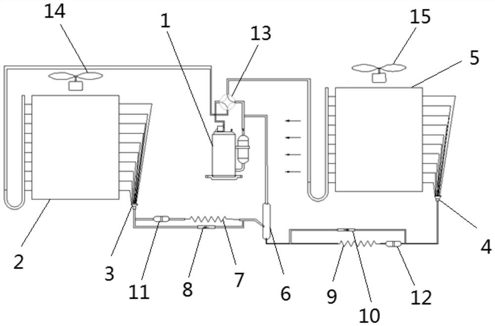
[0029] Such as figure 1 with 2 A specific implementation of the air source heat pump shown includes a compressor 1, a first heat exchanger 2, a first distributor 3, a first throttling structure, a second throttling structure, and a second distribution device 4 and the second heat exchanger 5.

[0030] A ga...


PUM


Abstract

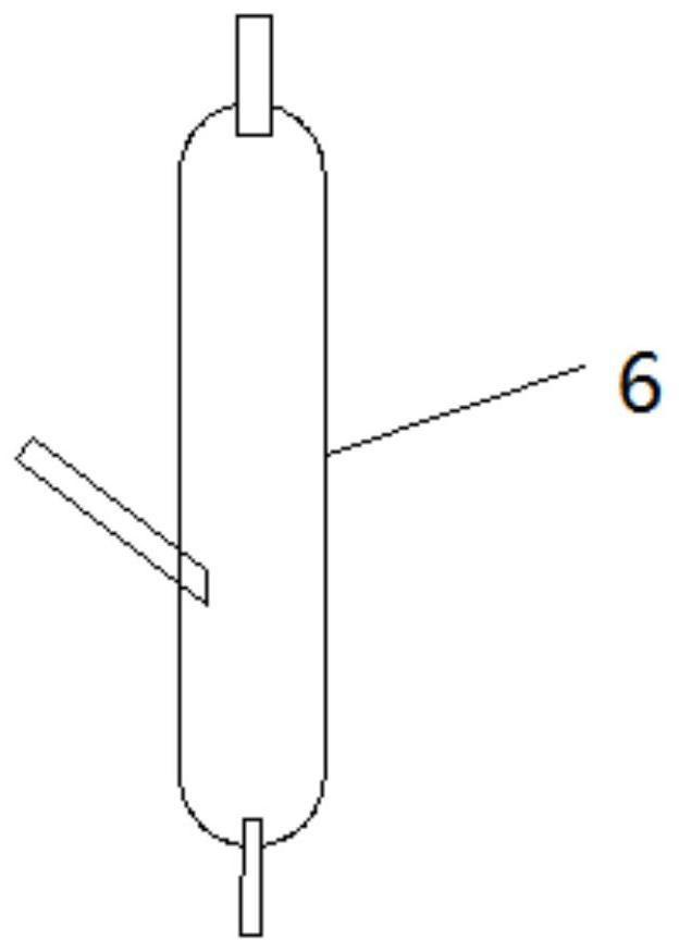
The invention relates to the technical field of heat pumps, in particular to an air source heat pump. The air source heat pump comprises a compressor, a first heat exchanger, a first throttling structure, a second throttling structure, a second heat exchanger and a gas-liquid separator. The compressor, the first heat exchanger, the first throttling structure, the second throttling structure and the second heat exchanger are sequentially and cyclically connected. The gas-liquid separator is arranged between the first throttling structure and the second throttling structure and is provided witha first opening, a second opening and a third opening, wherein the first opening and the second opening are connected with the first throttling structure and the second throttling structure correspondingly, and the third opening is connected with the compressor. The air source heat pump has the high heat exchange amount and heat exchange efficiency.

Description

technical field [0001] The invention relates to the technical field of heat pumps, in particular to an air source heat pump. Background technique [0002] A heat pump is a device that can obtain low-level heat energy from air, water or soil in nature, and perform work through electric energy to provide a high-level heat pump that can be used by people. The ideal thermodynamic cycle system of a heat pump consists of isobaric evaporation, isentropic compression, isobaric condensation, and isenthalpy throttling. gaseous state for efficient heat transfer. However, the heat pump cycle is a non-ideal thermodynamic cycle system, and the Freon at the outlet of the throttling element is generally in a gas-liquid two-phase mixed state. The wall forms an air film, which increases the heat transfer resistance of Freon and reduces the evaporation efficiency of liquid Freon. Therefore, the overall heat transfer capacity and heat transfer efficiency of the heat pump are greatly affected....

Claims


Application Information

Patent Timeline
IPC IPC(8): F25B30/06F25B41/04F25B41/06F25B43/00F25B13/00F25B30/02
CPCF25B13/00F25B30/02F25B30/06F25B43/00F25B43/003
Inventor 仇春伟郑丹庆沈黎明黄道德
Owner ZHEJIANG AMA & HIEN TECH
Learn More