
Self actuating speed synchronous tracking insertion gear-shifting gear

A technology of synchronous tracking and synchronous gears, which is applied to gear transmissions, belts/chains/gears, transmissions, etc., and can solve problems such as instability

Inactive Publication Date: 2014-07-02
何良智
View PDF0 Cites 0 Cited by
  • Summary
  • Abstract
  • Description
  • Claims
  • Application Information

AI Technical Summary

Problems solved by technology

[0002] The current hair-fork shift mechanism has a synchronous ring in the gear position, the speed is synchronized, and the precise real-time tracking is performed, especially when the gear is synchronously tracked at a high speed, it shows the problem of instability.

Method used


Image

  • Self actuating speed synchronous tracking insertion gear-shifting gear

Examples


Embodiment Construction

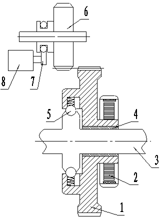
[0009] Below in conjunction with Fig. 1, describe in detail the concrete work situation that the present invention proposes, figure 1 A controllable clutch 5 is connected between the driven synchronous gear 1 and the output shaft 3, and the driven synchronous gear 1 is installed on the output shaft 3 through the oil bearing 4, and the other end of the driven synchronous gear 1 is equipped with a synchronous Tracking motor 2, driving wheel 6 and driven synchronous gear 1 are relatively installed, shift fork 7 and electromagnetic tension valve 8 are housed at one end of driving wheel 6.

[0010] Before the driving wheel 6 is inserted for shifting, the controllable clutch 5 disengages the driven synchronous gear 1, and the synchronous tracking motor 2 drives the driven synchronous gear 1 to rotate. The speed of the driven synchronous gear 1 is obtained by collecting the speed of the driving wheel 6. The speed signal is realized by driving the driven synchronous gear 1 by t...


PUM


Abstract

The invention relates to a self actuating speed synchronous tracking insertion gear-shifting gear. Before a driving wheel is inserted to conduct gear shifting, a controllable clutch enables a driven synchronous gear to be separated, a synchronous tracking motor drives the driven synchronous gear to rotate, driven synchronous gear synchronization is achieved by collecting speed signals of the driving wheel and driving the driven synchronous gear with the synchronous tracking motor, relative rest of opposite teeth can be achieved, at the time, the driving wheel is rapidly pushed to be inserted into the teeth of the driven synchronous gear by an electromagnetic pull force valve through a shifting fork, the controllable clutch then works to output power, and the gear shifting function is achieved.

Description

technical field [0001] The invention belongs to the technical field of equipment, and belongs to the self-driving speed synchronous tracking insertion shift gear. Background technique [0002] The current hair-fork shift mechanism has a synchronous ring in the gear position, the speed is synchronous, and the precise real-time tracking, especially the synchronous tracking of the teeth at a higher speed, shows the problem of instability. Contents of the invention [0003] The purpose of the present invention is to provide a self-driven speed synchronously tracking and inserting a shifting gear to realize the purpose of smooth shifting. [0004] Its purpose is achieved in this way, the self-driven speed synchronous tracking insertion shift gear is composed of a driven synchronous gear, a synchronous tracking motor, an output shaft, an oil bearing, a controllable clutch, a driving wheel, a shift fork, and an electromagnetic pull valve; A controllable clutch is connected be...

Claims


Application Information

Patent Timeline
Patent Type & Authority Applications(China)
IPC IPC(8): F16H3/12
CPCF16H63/30
Inventor 何良智
Owner 何良智
Learn More