Touch panel and manufacturing method thereof

A touch panel and substrate technology, which is applied in the fields of instruments, computing, electrical and digital data processing, etc., can solve problems such as the inability to meet the needs of narrow-frame touch display devices, and achieve the effect of improving signal attenuation.

Active Publication Date: 2019-03-15
TRENDON TOUCH TECHNOLOGY CORPORATION
View PDF5 Cites 0 Cited by
  • Summary
  • Abstract
  • Description
  • Claims
  • Application Information

AI Technical Summary

Problems solved by technology

However, due to the increase in the width of the wire 3, when the touch panel is applied to a touch display device, in order to prevent the wire 3 from being visible, the frame shielding area of ​​the touch display device (such as the invisible area of ​​a common touch mobile phone) will also be become wider, which cannot meet the product demand for narrow bezel touch display devices

Method used


Image

  • Touch panel and manufacturing method thereof
  • Touch panel and manufacturing method thereof
  • Touch panel and manufacturing method thereof

Examples


Embodiment Construction

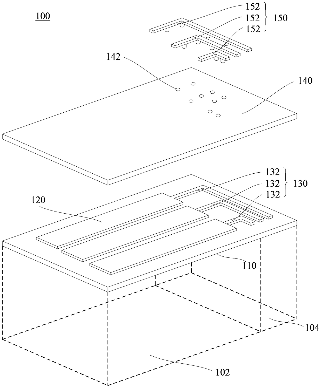
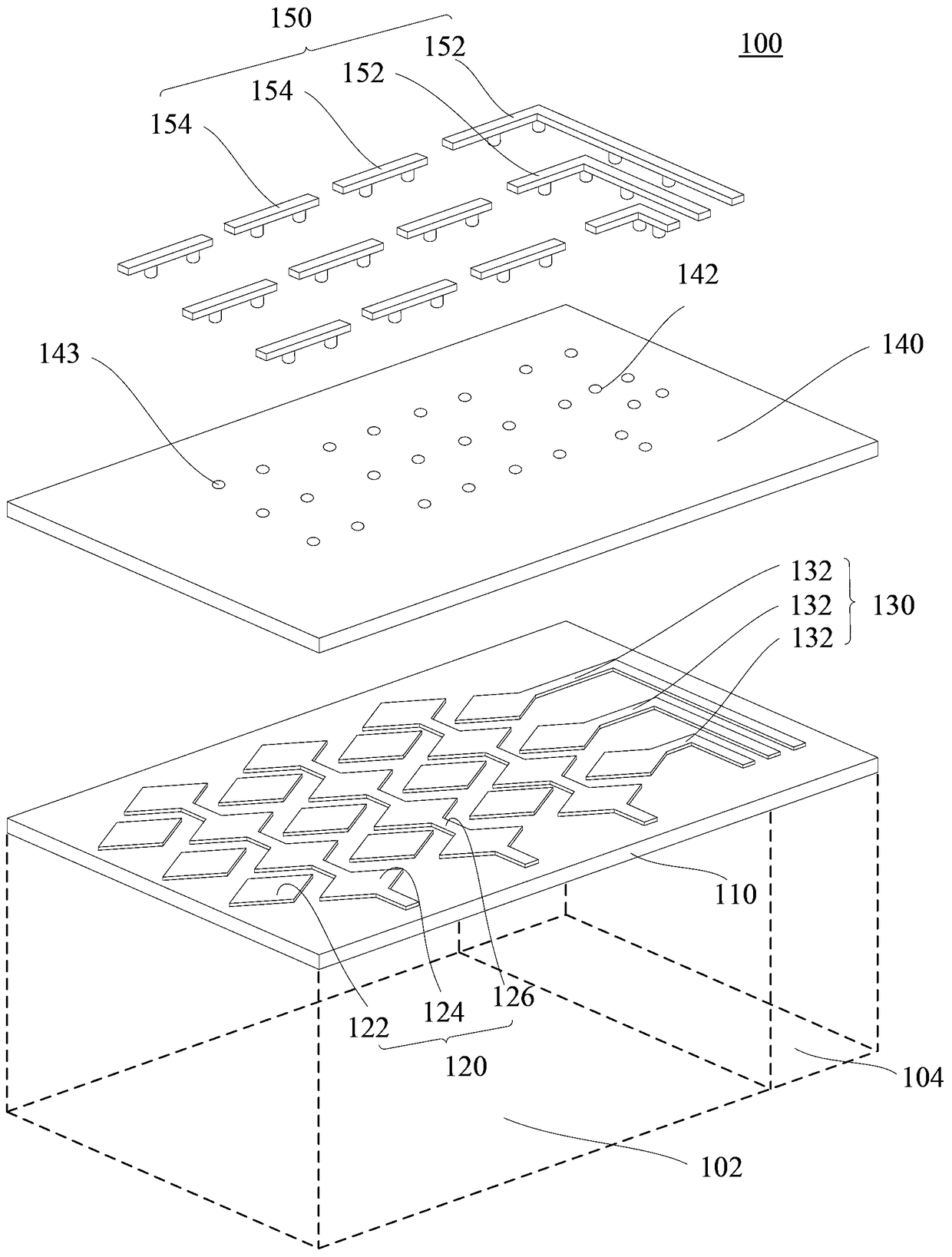
[0017] see figure 2 , is an exploded view of the touch panel of an embodiment. The touch panel 100 defines a sensing area 102 and a circuit area 104 located at the edge of the sensing area 102 . The touch panel 100 includes an electrode layer 120 , a first wire layer 130 , an insulating layer 140 and a second wire layer 150 . The position and quantity of the wiring area 104 can be adjusted according to the specific structure of the electrode layer 120 and the number of the first wiring 132 contained in the first wiring layer 130 , for example, the wiring area 104 can be located on one side or more than one side of the electrode layer 120 . The electrode layer 120 is located in the sensing area 102 , and the first wire layer 130 is located in the circuit area 104 and is electrically connected to the electrode layer 120 . The second wire layer 150 is electrically connected to the first wire layer 130 in the wiring area 104 . The insulating layer 140 can be disposed between th...


PUM


Abstract

A touch panel defines a sensing area and a circuit area at the edge of the sensing area. The touch panel is characterized by comprising an electrode layer in the sensing area, a first lead layer in the circuit area, a second lead layer, and an insulating layer; the first lead layer is electrically connected with the electrode layer; the second lead layer is electrically connected with the first lead layer in the circuit area; in the circuit layer, the insulating layer is disposed between the first lead layer and the second lead layer and provided with a plurality of through holes; the first lead layer and the second lead layer are electrically connected through the first through holes. The invention further discloses a manufacture method of the touch panel. The touch electrode structure is applicable to touch panels of large size; the attenuation problem in signals generated by large-size panels is improved without enlarging the width of a mask area of a touch panel frame.

Description

technical field [0001] The invention relates to touch technology, in particular to a touch panel and a manufacturing method thereof. Background technique [0002] like figure 1 Shown is a schematic structural diagram of a traditional touch panel. The touch panel 10 includes first electrodes 1 and second electrodes 2 arranged vertically and alternately. Both ends of the first electrode 1 and the second electrode 2 are led out through the wire 3 and converged to the controller 4 . The touch of the electrodes by an external conductive object will cause some electrical parameters on the first electrode 1 and the second electrode 2 to change. Realize the touch function. It can be understood that as the size of the touch panel increases, the path through which the wire 3 converges from one end to the controller 4 will also become longer. According to the resistance law R=ρL / S (ρ is the resistivity of the material of the wire 3, L is The length of the wire 3 , S is the cross-s...

Claims


Application Information

Patent Timeline
Patent Type & Authority Patents(China)
IPC IPC(8): G06F3/041
Inventor 刘振宇李禄兴
Owner TRENDON TOUCH TECHNOLOGY CORPORATION
Why Eureka
Try Eureka