
Gas turbine engine with variable overall pressure ratio

一种燃气涡轮、发动机的技术,应用在燃气轮机装置、发动机功能、机器/发动机等方向,能够解决增大压缩机成本等问题

Active Publication Date: 2014-07-02
UNITED TECH CORP
View PDF6 Cites 2 Cited by
  • Summary
  • Abstract
  • Description
  • Claims
  • Application Information

AI Technical Summary

Problems solved by technology

Consequently, the clutch is exposed to temperatures up to approximately 1000°F, which necessitates the use of high temperature clutch components, thereby increasing the cost of the compressor

Method used


Image

  • Gas turbine engine with variable overall pressure ratio
  • Gas turbine engine with variable overall pressure ratio
  • Gas turbine engine with variable overall pressure ratio

Examples


Embodiment Construction

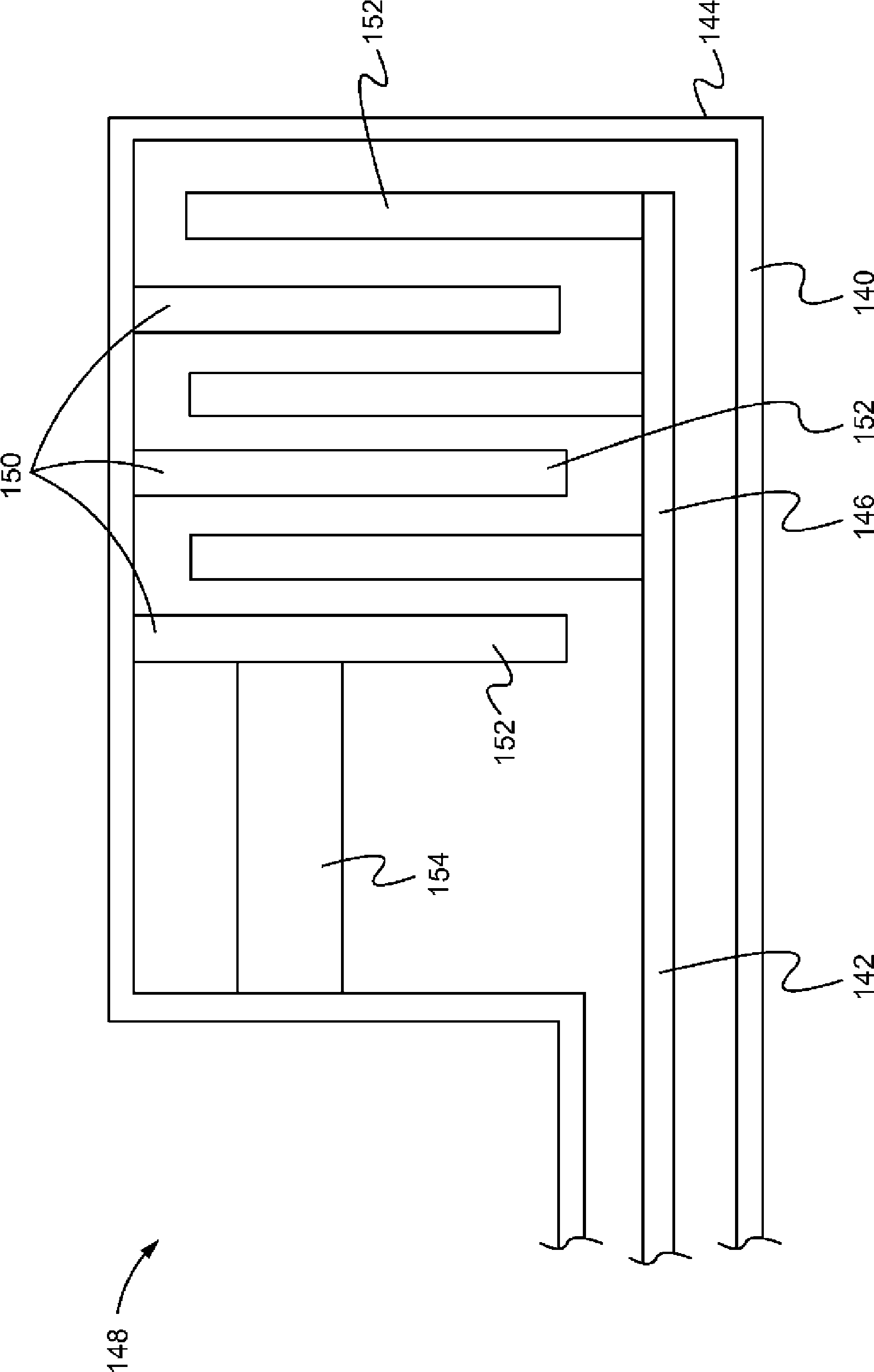
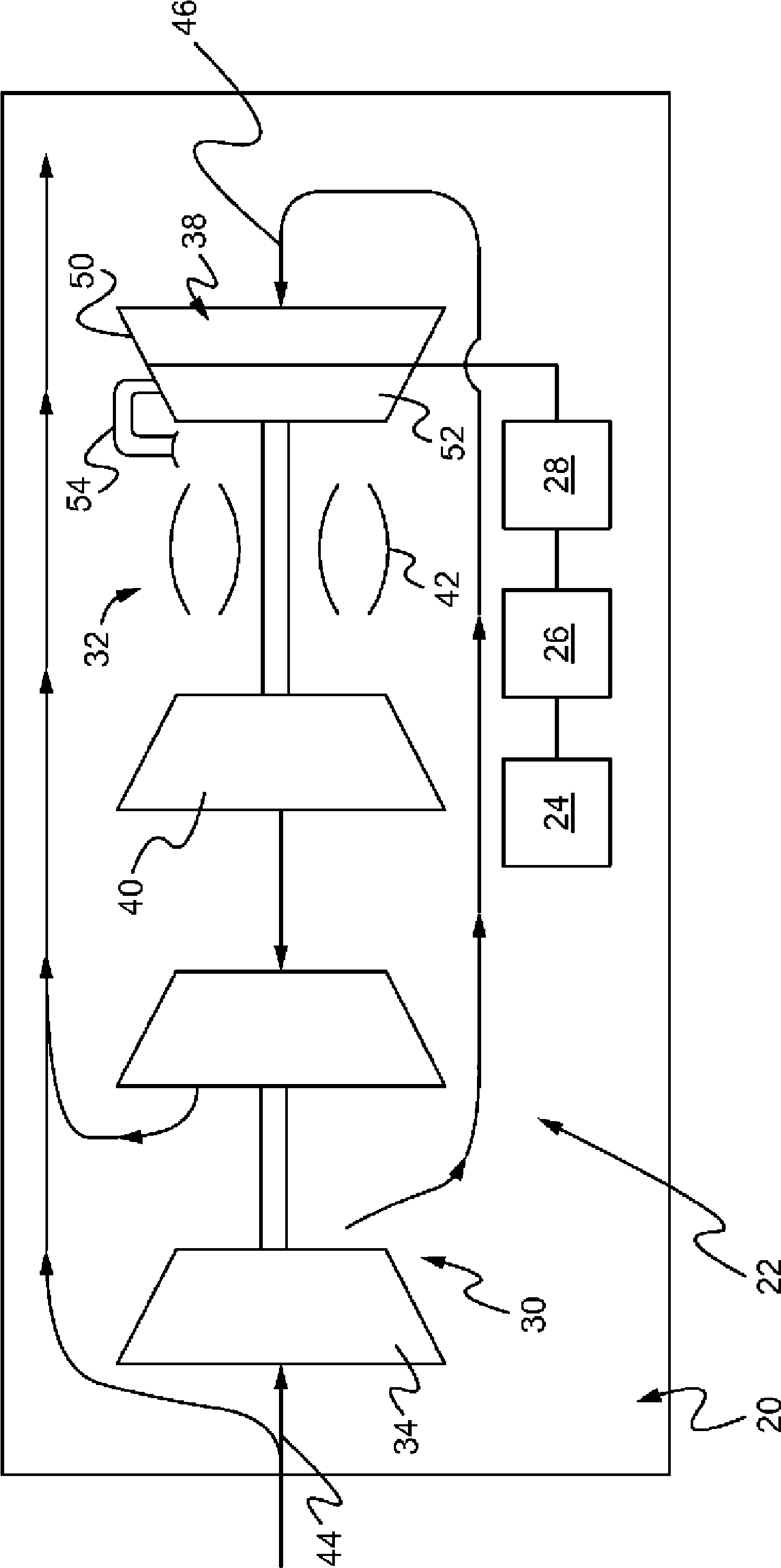
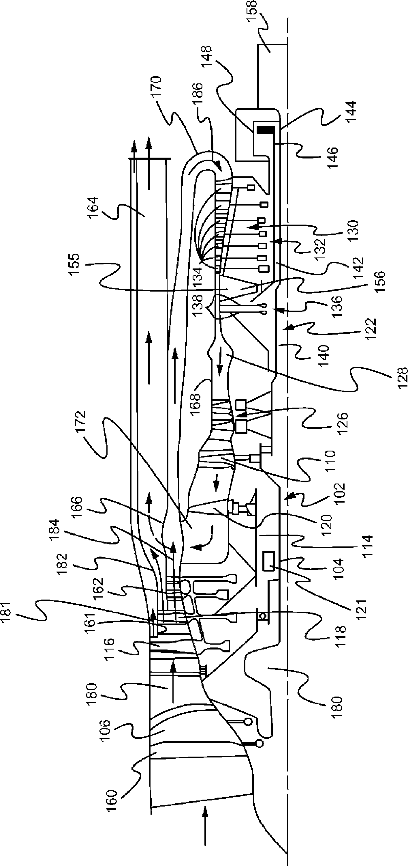
[0022] An exemplary embodiment of a gas turbine engine having a variable overall pressure ratio ("OPR") is disclosed herein. Each engine includes a high pressure compressor having at least a primary stage with a primary set of rotors and a secondary stage with a secondary set of rotors. A clutch is provided to selectively engage the secondary rotor with the primary rotor. During operation of a vehicle having an exemplary gas turbine engine, engagement of the clutch may be controlled based on the vehicle travel mode. For example, on an aircraft, a clutch may be disengaged during a takeoff mode and engaged during a loitering mode. During high propulsion conditions during takeoff, the clutch may be disengaged to stop power to the secondary of the high pressure compressor, thereby reducing turbine inlet temperature ("T3"). By separating the secondary of the high pressure compressor, the OPR is also reduced. Conversely, when the aircraft is at high altitude and cruising in loite...


PUM


Abstract

A gas turbine engine has a variable overall pressure rate (OPR). The engine includes a high pressure compressor having at least a primary stage having a set of primary rotors and a secondary stage having a set of secondary rotors. A clutch is provided to selectively engage the secondary rotors with the primary rotors. Engagement of the clutch may be controlled based on the vehicle travel mode, such as disengaging during a takeoff mode to reduce turbine entry temperature and engaging during a loiter mode to increase OPR.

Description

technical field [0001] The present disclosure relates generally to gas turbines, and more particularly to an apparatus and method for providing variable overall pressure ratios in a gas turbine engine. Background technique [0002] Gas turbine engines are commonly used to propel aircraft. The efficiency and performance of a gas turbine engine can vary depending on the form of the engine and the flight parameters of the aircraft. Typically, however, the operating efficiency of conventional gas turbine engines used in aircraft is not optimized throughout the flight envelope. More specifically, operating efficiency typically includes several components, such as propulsion efficiency and thermal efficiency, with highest values ​​at different power settings. The overall pressure ratio (OPR) of a gas turbine engine can affect when the highest propulsion and thermal efficiencies are achieved. In most conventional aircraft, the OPR is fixed and thus the active components typicall...

Claims


Application Information

Patent Timeline
Patent Type & Authority Applications(China)
IPC IPC(8): F02C7/36F02C3/14F02C7/32F02K3/105
CPCF02C7/36F02C3/145F05D2220/76F02C7/32F05D2260/96F02K3/105F05D2260/4023
Inventor J.W.诺里斯D.B.库普拉蒂斯G.M.斯特森
Owner UNITED TECH CORP
Learn More