Integrated automatic microscopic welding equipment

A technology of welding equipment and automatic spot welding, which is applied in welding equipment, resistance welding equipment, welding power supply, etc. It can solve the problems of independent adjustment, overall weight of the machine head, and the accuracy of electrode force cannot meet the requirements of spot welding, etc., to achieve accurate electrode force Effect of improving output and spot welding accuracy

Active Publication Date: 2014-07-09
GUANGZHOU MICRO WELDING EQUIP
View PDF10 Cites 3 Cited by
  • Summary
  • Abstract
  • Description
  • Claims
  • Application Information

AI Technical Summary

Problems solved by technology

[0002] The CN1382557 patent announced by the Chinese Patent Office on December 4, 2002 discloses a double welding head spot welding machine, which mainly improves the welding head clamp, and the purpose is to optimize the welding effect, and the double welding head spot welding machine is theoretically Obviously, it can improve the efficiency of spot welding. However, the double welding head spot welding machine disclosed in the CN1382557 patent cannot independently adjust the electrode force of each parallel electrode and the electrical parameters of the welding energy output. Therefore, How to make the spot welding machine with double welding heads not only improve the efficiency of spot welding, but also obtain more accurate spot welding effect is one of the problems to be solved urgently in the industry
[0003] Specifically, the traditional resistance welding spot welding equipment has the following characteristics: First, spot welding is performed with a single solder spot. Since most electronic components have two lead-out contacts that need to be spot-welded, therefore, equipment with multiple solder spots The spot welding machine will be able to provide higher spot welding efficiency; Second, the accuracy of the electrode force at the traditional resistance point can reach ±10N, while the electrode force commonly used in practice generally only needs to be below 10N, so the electrode force achieved by the traditional technology The accuracy cannot meet the requirements of spot welding
It can be seen that the spot welding machine is a kind of precision equipment, and the spot welding machine with multiple welding points is more difficult to grasp due to the further complexity of its structure, such as the overall weight of the machine head and the increase in power during operation.

Method used


Image

  • Integrated automatic microscopic welding equipment
  • Integrated automatic microscopic welding equipment
  • Integrated automatic microscopic welding equipment

Examples


Embodiment Construction

[0040] The present invention will carry out overall introduction according to following each aspect as follows: 1, overall structure; 2, two spot welding machine heads that are installed into one; 3, the head frame of spot welding machine; 4, resistance welding power supply; head clip.

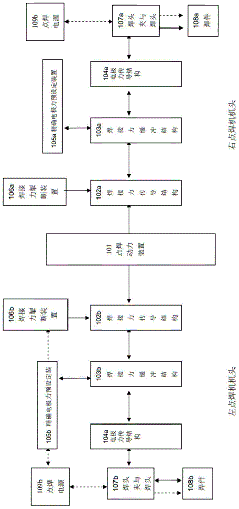
[0041] 1. First, combine the attached figure 1 Introduce the general structural block diagram of the present invention.

[0042] figure 1 While showing the overall structural frame of the spot welding equipment of the present invention, it also shows its structural principle, which includes a spot welding power device 101, welding force transmission structures 102a, 102b, welding force buffer structures 103a, 103b, electrode force transmission Structure 104a, 104b, precise electrode force preset device 105a, 105b, welding force breaking device 106a, 106b, welding head clip and welding head 107a, 107b, and the electrode force applied by the spot welding equipment of the present invention for ...


PUM


Abstract

The invention relates to welding automation, in particular to integrated automatic microscopic welding equipment. Two welding pieces are automatically welded simultaneously by two spot welding machine heads mounted integrally, two welding head clamps arranged side by side, two spot welding power sources and an automatic spot welding power plant; and reliability consistency on welding can be guaranteed by independently adjusting welding parameters of two parallel electrode welding heads. A clearance between the two welding head clamps arranged side by side is adjustable by modifying frames of the spot welding machine heads. The integrated automatic microscopic welding equipment is brand-new automatic welding equipment for production and manufacture on electronic components.

Description

technical field [0001] The invention relates to resistance welding microscopic welding technology, in particular to an integrated automatic microscopic welding equipment. Background technique [0002] The CN1382557 patent announced by the Chinese Patent Office on December 4, 2002 discloses a double welding head spot welding machine, which mainly improves the welding head clamp, and the purpose is to optimize the welding effect, and the double welding head spot welding machine is theoretically Obviously, it can improve the efficiency of spot welding. However, the double welding head spot welding machine disclosed in the CN1382557 patent cannot independently adjust the electrode force of each parallel electrode and the electrical parameters of the welding energy output. Therefore, How to make the spot welding machine with double welding heads not only improve the efficiency of spot welding, but also obtain more accurate spot welding effect is one of the problems to be solved u...

Claims


Application Information

Patent Timeline
Patent Type & Authority Applications(China)
IPC IPC(8): B23K11/11B23K11/36
CPCB23K11/11B23K11/255B23K11/312B23K11/318B23K11/115B23K11/241B23K11/31
Inventor 杨仕桐
Owner GUANGZHOU MICRO WELDING EQUIP
Why Eureka
Try Eureka