
Stereo display system

A stereoscopic display and stereoscopic image technology, applied in the field of projection systems, can solve problems such as small viewing angle and low resolution

Active Publication Date: 2014-07-09
IND TECH RES INST
View PDF5 Cites 4 Cited by
  • Summary
  • Abstract
  • Description
  • Claims
  • Application Information

AI Technical Summary

Problems solved by technology

[0003] At present, there are a few naked-view stereoscopic display technology products on the market, but they all have shortcomings such as small viewing angle and low resolution, making it difficult to apply to occasions that require high image

Method used


Image

  • Stereo display system
  • Stereo display system
  • Stereo display system

Examples


Embodiment Construction

[0079] In order to make the above-mentioned features and advantages of the present invention more comprehensible, the following specific embodiments are described in detail together with the accompanying drawings.

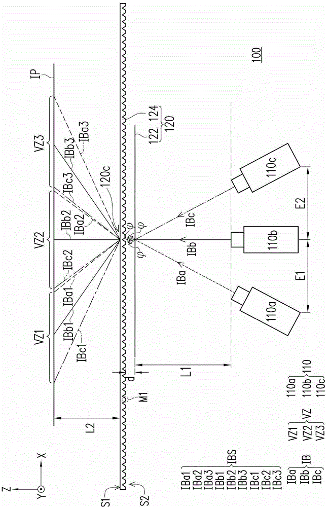
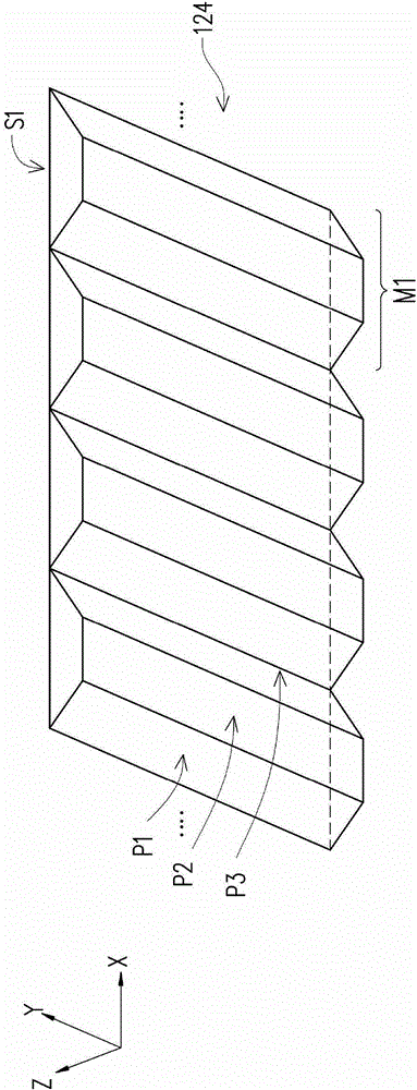
[0080] figure 1 It is a stereoscopic display device in an embodiment of the present invention, please refer to figure 1 , in this embodiment, the stereoscopic display system 100 includes a plurality of projection devices 110 and a screen module 120 . The projection device 110 is used for projecting a plurality of image beams IB respectively. The screen module 120 is disposed in front of the projection devices 110 , wherein the image beams IB are transmitted toward the screen module 120 . The screen module 120 includes a light diffusion layer 122 and a light splitting layer 124 . In this embodiment, the distance d between the light diffusion layer 122 and the light splitting layer 124 is, for example, 100 microns, but the present invention is not limited thereto....


PUM


Abstract

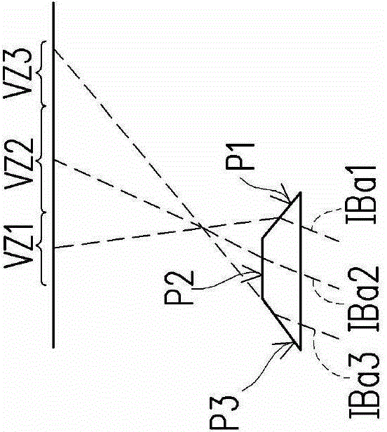
A stereo display system including a plurality of projection apparatuses and a screen module is provided. The projection apparatuses project a plurality of image beams. The screen module is disposed in front of the projection apparatuses, wherein the image beams are transmitted toward the screen module. The screen module includes a light diffusion layer and a beam splitting layer. The light diffusion layer has at least one diffusion direction, and the light diffusion layer diffuses the image beams with a diffusion angle. The light diffusion layer is disposed between the beam splitting layer and the projection apparatuses, wherein each of the image beams is divided into a plurality of sub image beams by the beam splitting layer. The sub image beams of each image beam transmit with different angles, such that the image beams form a plurality of stereo image viewing zones after passing through the screen module.

Description

technical field [0001] The present invention relates to a projection system, and in particular to a stereoscopic projection system. Background technique [0002] With the advancement of display technology and various technological processes in recent years, various display devices have been invented, such as compact handheld displays, high-quality display screens, and even three-dimensional displays that can almost be faked. Its lifelike image display quality , so that the imagination of human beings can gallop in it. Among them, the rapid development of 3D display technology and the substantial increase in consumer demand have led to the shipment of 3D displays reaching one million in 2010. With the rapid decline in prices and the gradual popularization of content, the 3D display industry will continue to grow in the next few years. Rapid development. However, most of the 3D displays currently on the market need to wear special glasses to see 3D images, such as common pol...

Claims


Application Information

Patent Timeline
IPC IPC(8): G03B35/20G03B21/60G02B27/22H04N13/04G02B30/27H04N13/363
CPCG03B21/60G03B35/20G03B35/24H04N13/363H04N13/302G02B30/27
Inventor 陈长营蔡朝旭吴昌硕
Owner IND TECH RES INST
Learn More