Multi-dimensional images system for digital image input and output

Active Publication Date: 2004-07-15
NIMS JERRY C
View PDF18 Cites 129 Cited by
  • Summary
  • Abstract
  • Description
  • Claims
  • Application Information

AI Technical Summary

Problems solved by technology

When a picture is taken through a conventional camera, however, there is no parallax information available.
It is not available because the conventional camera has only a single lens and, hence, each picture reflects a single viewing position.
Many users find these uncomfortable to wear for extended periods.
This significantly changes and reduces the range of colors of the viewed three-dimensional image.
A result is that the scene may appear unnatural.
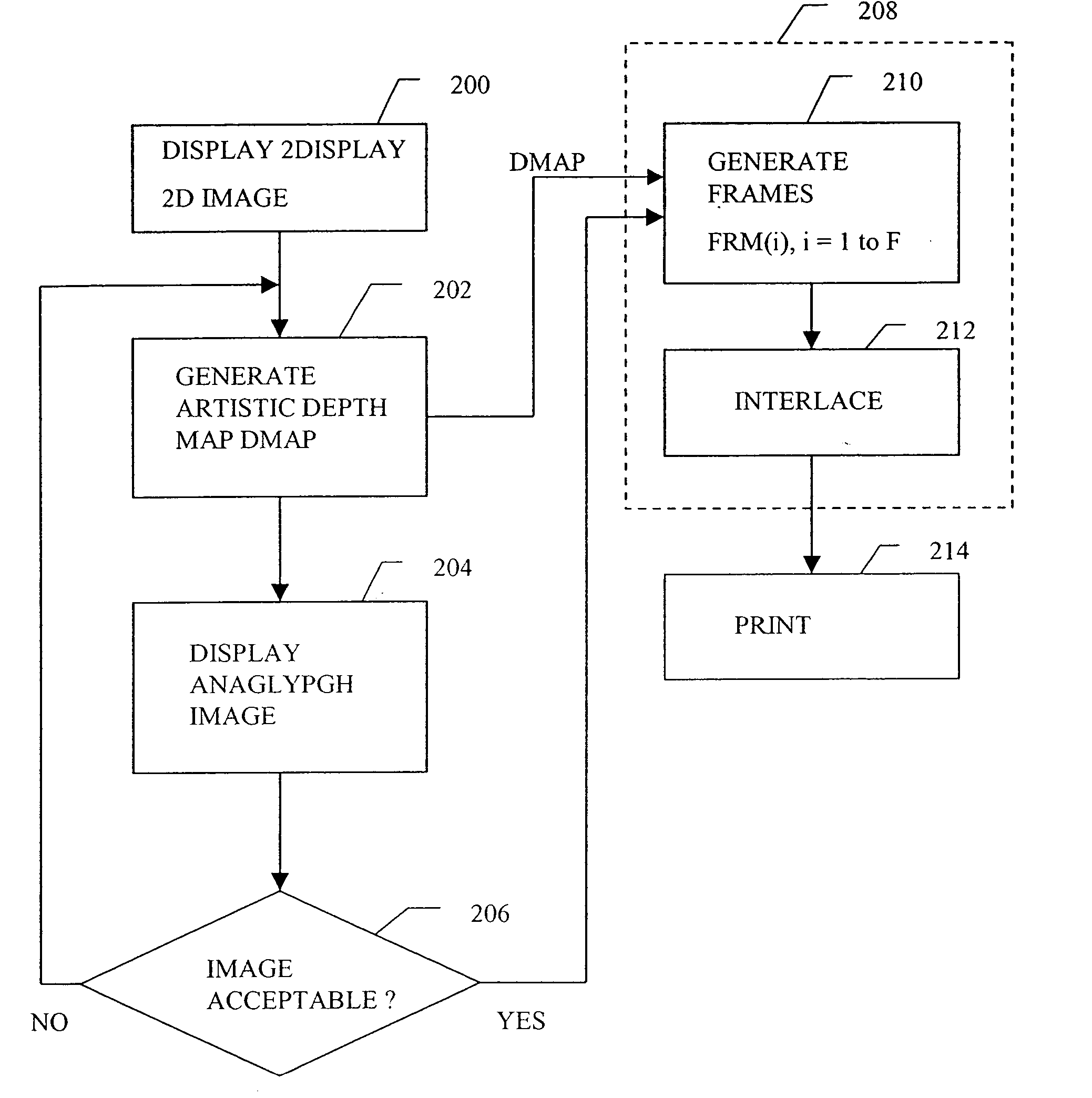
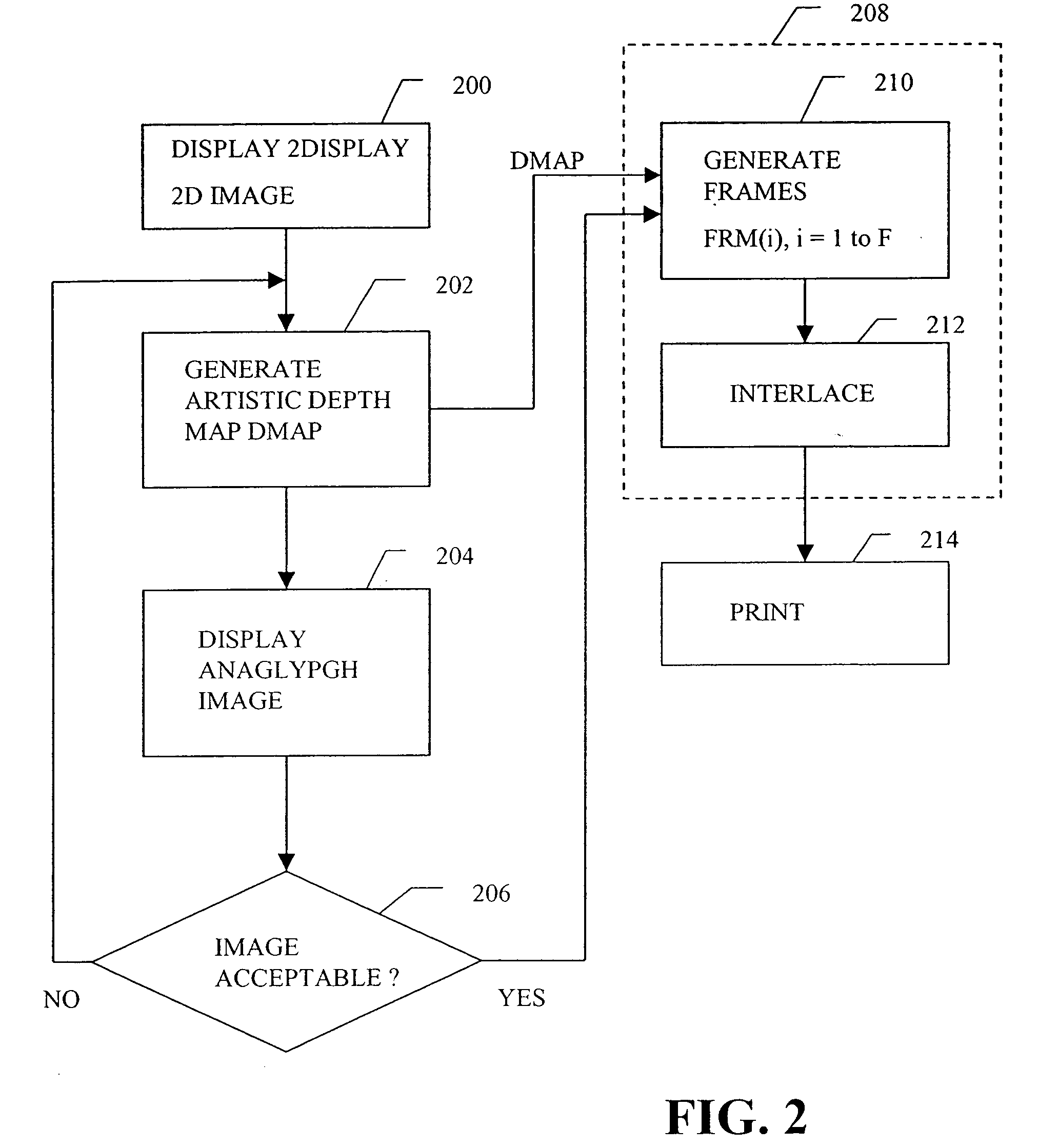
There are difficulties encountered in processing and formatting a two-dimensional image for viewing as a three-dimensional image through a lenticular medium.
One difficulty is that the objects in the image must be placed on particular depth planes.
A related difficulty is that the optimum number of planes in the depth direction depends on numerous factors, including the type of lenticular screen, the size of the image, the distance from which the image will be viewed through the lenticular screen, and the particular type, size and relative positions of the objects in the original scene.
Therefore, the user must be sophisticated enough to calculate this number, or a default number must be used which may not be optimal for all situations.
The above problems can become particularly troublesome because the desired three-dimensional quality provided by the processing cannot be observed until the processing is completed and the rasterized, interlaced image is printed on a lentic

Method used


Image

  • Multi-dimensional images system for digital image input and output
  • Multi-dimensional images system for digital image input and output
  • Multi-dimensional images system for digital image input and output

Examples


Embodiment Construction

[0057] Referring to FIG. 1 a first example system will be described. The FIG. 1 example includes a processing resource 10 connected to a display 12, a user command input interface 14, and a printer 16. The processing resource 10 includes a data processor 18, a program storage resource 20 and a data storage resource 22. The processing resource 10 may be an off-the-shelf general-purpose programmable computer, such as is available from numerous vendors. An example is a Dell Optiplex.TM. personal computer (PC), having an Intel Pentium IV or equivalent processor, 256 Mbytes of random access memory (RAM), a DVD-CD disc drive, and a 60 GByte internal magnetic disc drive, running under, for example, the Microsoft Windows XP.TM. operating system. The Dell Optiplex.TM. is merely an example implementation of the processing resource 10. Other implementations include, for example, an Apple G4 iBook.TM. or Powerbook.TM. computer, running under Apple's OS9 "Classic" or OSX.TM. Unix-type operating ...


PUM


Abstract

A two-dimensional image is displayed and a grey level image is drawn on said two-dimensional image defining a depth map. A stereo image pair is generated based on the depth map and an anaglyph image of the stereo image pair is displayed. Edits of the depth map are displayed by anaglyph image. A plurality of projection frames are generated based on the depth map, and interlaced and printed for viewing through a micro optical media. Optionally, a layered image is extracted from the two-dimensional image and the plurality of projection frames have an alignment correction shift to center the apparent position of the image. A measured depth map is optionally input, and a stereo pair is optionally input, with a depth map calculated based on the pair. The user selectively modifies the calculated and measured depth map, and the extracted layers, using painted grey levels. A ray trace optionally modifies the interlacing for optimization to a particular media.

Description

DESCRIPTION[0001] Priority of this application is based on U.S. Provisional Application No. 60 / 406,953, filed on Aug. 30, 2002, which is hereby incorporated by reference.[0002] This invention relates generally to a method and apparatus for three-dimensional viewing and, more particularly, to inputting, formatting, processing and fixing image information for three-dimensional viewing through a lenticular medium.DESCRIPTION OF THE RELATED ART[0003] Human vision employs two eyes spaced approximately four inches apart. The spacing provides each eye with a slightly different viewing position, whereby each eye sees a slightly different image, the difference between the two being generally referenced as "parallax". The human brain's processing of this parallax is a significant reason for our perception of depth when observing a scene, in other words, for humans seeing in three dimensions.[0004] When a picture is taken through a conventional camera, however, there is no parallax information...

Claims


Application Information

Patent Timeline
IPC IPC(8): G06FG06T15/00H04N13/00
CPCH04N13/026H04N13/261G06T15/00
Inventor NIMS, JERRY C.
Owner NIMS JERRY C
Why Eureka
Try Eureka