Device and method for decoding HDTV video

a technology of video decoding and video, applied in the field of hdtv video decoding, can solve the problems of increased cost and severe errors of the conventional hdtv video decoding device, and achieve the effect of good picture quality

Inactive Publication Date: 2000-08-15
LG ELECTRONICS INC
View PDF13 Cites 91 Cited by
  • Summary
  • Abstract
  • Description
  • Claims
  • Application Information

AI Technical Summary

Benefits of technology

An object of the present invention is to provide a device for decoding an HDTV video, in which a frame memory capacity for all the bit streams of progressive scanned image and interlace scanned image encoded to the MPEG-2 is reduced by 1 / 2 in horizontal and vertical directions and conducts an IDCT and motion compensation to suit to the reduced frame memory size, and still allows to obtain a good picture quality.

Problems solved by technology

However, though the conventional HDTV video decoder can effectively decode a bit stream of a progressive scanned image compressed according to the MPEG-2 standard, and having a frame that is composed of pixels formed at the same time, the conventional HDTV video decoder experiences severe errors when decoding an interlace scanned image having a frame that is composed of two fields of different time bases.
As this vertical decimation is not practicable, an 8.times.4 IDCT and a frame memory reduced by 1 / 2 in a horizontal direction are used, which results in increased costs.

Method used


Image

  • Device and method for decoding HDTV video
  • Device and method for decoding HDTV video
  • Device and method for decoding HDTV video

Examples


first embodiment

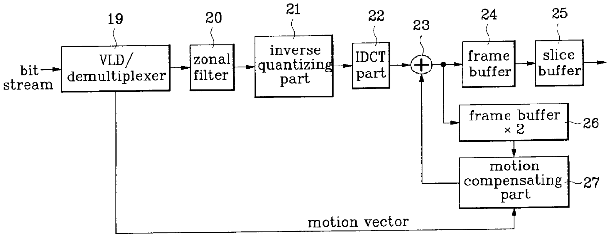
FIG. 9 illustrates a block diagram of an HDTV video decoder circuit in accordance with the present invention which can decimate an interlace scanned image having a frame with two fields of different time bases without losing its time information and which can conduct a compensation suited to the time information, thereby improving a picture quality of the decimated image.

Referring to FIG. 9, the HDTV video decoder circuit in accordance with a first embodiment of the present invention includes a VLD / demultiplexer 28 for conducting a variable length decoding of a received bit stream to separate the bit stream into motion vectors, quantizing values, and 8.times.8 DCT coefficients, an 8.times.4 zonal filter 29 for removing horizontal high frequency regions from the quantizing values and the 8.times.8 DCT coefficients received from the VLD / demultiplexer 28, an inverse quantizing part 30 for quantizing the 8.times.4 DCT coefficients from the zonal filter 29 according to the quantizing val...

second embodiment

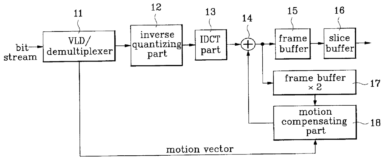
FIG. 19 illustrates a block diagram of an HDTV video decoder circuit in accordance with a second embodiment of the present invention, in which an adaptive vertical decimating part removes averages of adjacent even and odd line pixels in decimating odd fields of an interlace scanned video signal in a vertical direction by 1 / 2 to produce even lines and odd lines fit to display lines, that eliminates necessity for the line position correcting part.

Referring to FIG. 19, the HDTV video decoder circuit in accordance with a second embodiment of the present invention includes a VLD / demultiplexer 53 for conducting a variable length decoding of a received bit stream to separate the bit stream into motion vectors, quantizing values and 8.times.8 DCT coefficients, an 8.times.4 zonal filter 54 for removing horizontal high frequency regions from the quantizing values and the 8.times.8 DCT coefficients received from the VLD / demultiplexer 53, an inverse quantizing part 55 for quantizing the 8.times...


PUM


Abstract

HDTV video decoder circuit is disclosed, which has an +E,fra 1 / 4+EE size frame memory for a progressive scanned or interlace scanned video and yet can conduct IDCT and motion compensation to fit to the reduced frame memory size, which, in comparison to a conventional MPEG-2 video decoder which uses a 4x4 IDCT that requires +E,fra 1 / 4+EE frame memory in encoding an interlace scanned image into frame picture only to lose field information of the image resulting in a significant damage to the picture quality, facilitates to maintain the field information as it was resulting in an improvement in the picture quality.

Description

1. Field of the InventionThe present invention relates to an HDTV video decoder and, more particularly, to an HDTV(High Definition TV) video decoder circuit having a 1 / 4 size frame memory for a progressive scanned or interlace scanned video which is capable of conducting a IDCT(Inverse Discrete Cosine Transform) and motion compensation to fit to the reduced frame memory size.2. Discussion of the Related ArtThe GA(Grand Alliance) HDTV system, which is the U.S.A. HDTV standard, has video compression and multiplexing techniques following the MPEG-2(Moving Picture Experts Group-2) standards. It also has the capability for plural broadcasting video formats including with 24 Hz 30 Hz progressive scanning systems, and a 60 Hz interlaced scanning system for 1920.times.1080 pixels, and 24 Hz, 30 Hz and 60 Hz progressive scanning systems for 1280.times.720 pixels.A conventional HDTV video decoding device will be explained with reference to the attached drawings.FIG. 1 illustrates a block diag...

Claims


Application Information

Patent Timeline
Patent Type & Authority Patents(United States)
IPC IPC(8): G06T9/00H04N7/30H04N7/50H04N7/26H04N7/24
CPCH04N19/176H04N19/172H04N19/513H04N19/122H04N19/102H04N19/61H04N19/132H04N19/16H04N19/18H04N19/184H04N19/44H04N19/423H04N19/59H04N19/50
Inventor KIM, JIN-GYEONGLYU, HWA-YOUNG
Owner LG ELECTRONICS INC
Why Eureka
Try Eureka