Motion vector coding and decoding in interlaced frame coded pictures

a technology of interlaced frame coded pictures and motion vectors, applied in the field of interlaced video coding and decoding, can solve the problems of large storage and transmission capacity of digital video, lossless compression, and most computers and computer networks lack the resources to process raw digital video, so as to reduce temporal redundancy, reduce entropy, and reduce the effect of ra

Active Publication Date: 2005-03-10
MICROSOFT TECH LICENSING LLC
View PDF99 Cites 87 Cited by
  • Summary
  • Abstract
  • Description
  • Claims
  • Application Information

AI Technical Summary

Benefits of technology

One of the primary methods used to achieve data compression of digital video sequences in the international standards is to reduce the temporal redundancy between pictures. These popular compression schemes (MPEG-1, MPEG-2, MPEG-4, H.261, H.263, etc.) use motion estimation and compensation. For example, a current frame is divided into uniform square regions (e.g., blocks and/or macroblocks). A matching region for each current region is specified by sending motion vector information for the region. The motion vector indicates the location of the region in a previously coded (and reconstructed) reference frame that is to be used as a predictor f...

Problems solved by technology

Digital video consumes large amounts of storage and transmission capacity.
Most computers and computer networks lack the resources to process raw digital video.
Compression can be lossless, in which quality of the video does not suffer but decreases in bit rate are limited by the complexity of the video.
Or, compression can be lossy, in which quality of the video suffers but decreases in bit rate are more dramatic.
These international standards are limited in several important ways.
Using median prediction when candidates are set to 0 often produces skewed motion vector predictors.
T...

Method used


Image

  • Motion vector coding and decoding in interlaced frame coded pictures
  • Motion vector coding and decoding in interlaced frame coded pictures
  • Motion vector coding and decoding in interlaced frame coded pictures

Examples


Embodiment Construction

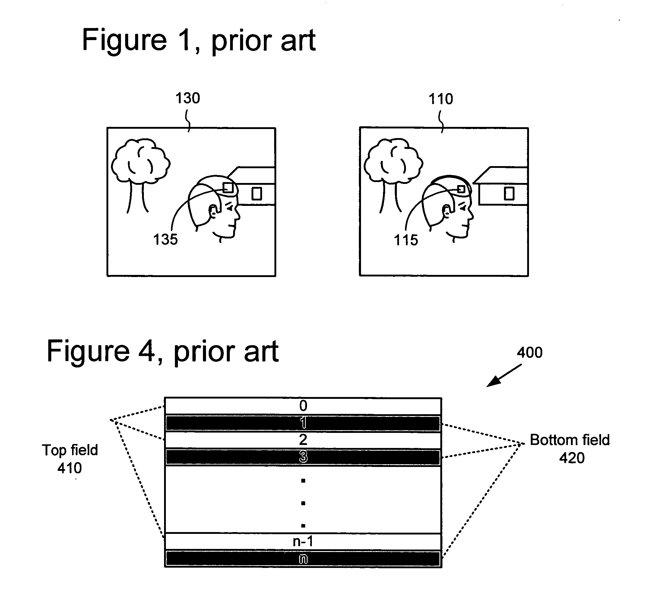
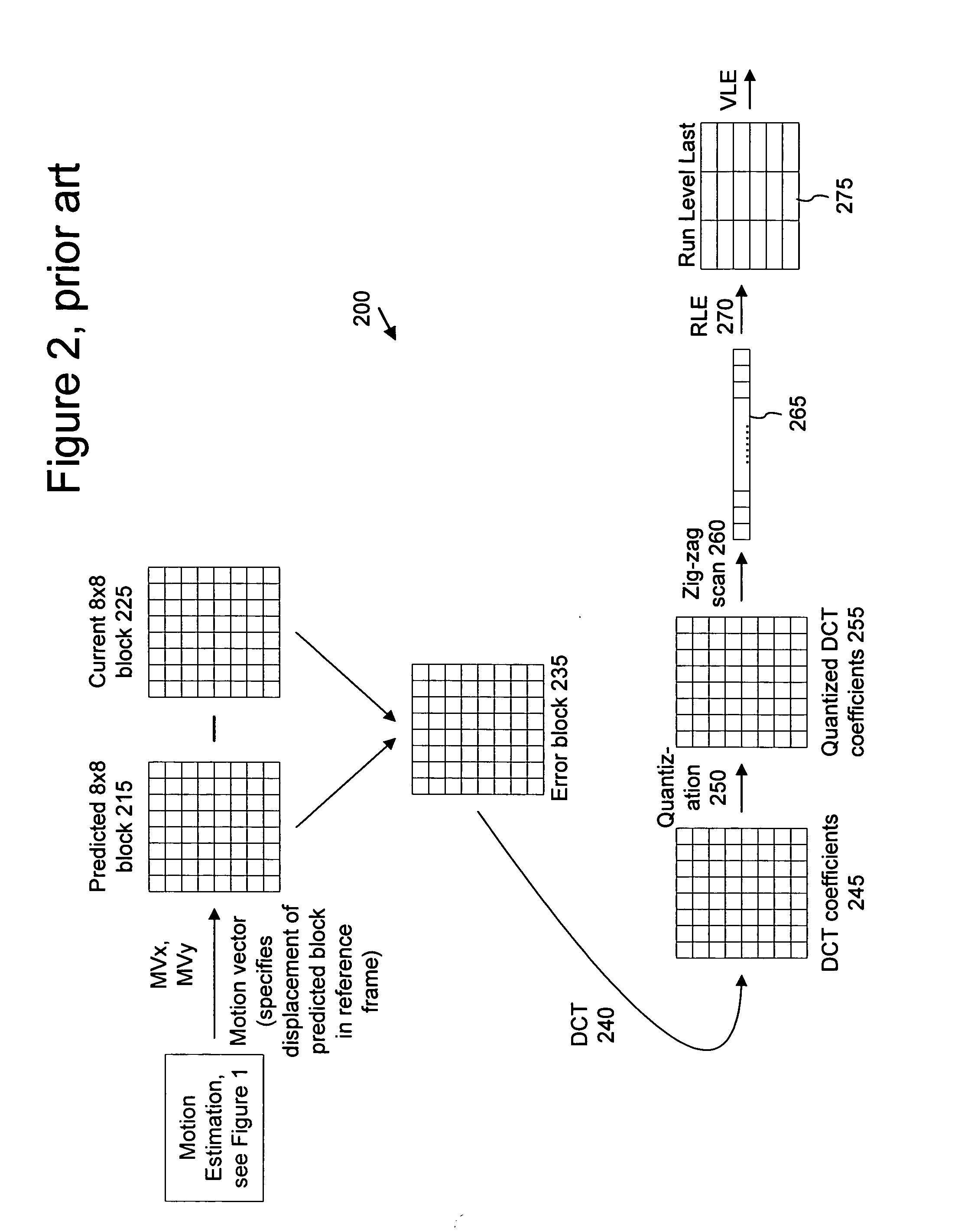
The present application relates to techniques and tools for efficient compression and decompression of interlaced video. In various described embodiments, a video encoder and decoder incorporate techniques for encoding and decoding interlaced video, and corresponding signaling techniques for use with a bit stream format or syntax comprising different layers or levels (e.g., sequence level, frame level, field level, macroblock level, and / or block level).

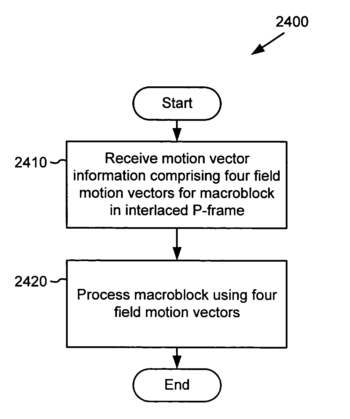
Various alternatives to the implementations described herein are possible. For example, techniques described with reference to flowchart diagrams can be altered by changing the ordering of stages shown in the flowcharts, by repeating or omitting certain stages, etc. As another example, although some implementations are described with reference to specific macroblock formats, other formats also can be used. Further, techniques and tools described with reference to forward prediction may also be applicable to other types of predictio...


PUM


Abstract

In one aspect, an encoder/decoder receives information for four field motion vectors for a macroblock in an interlaced frame-coded, forward-predicted picture and processes the macroblock using the four field motion vectors. In another aspect, an encoder/decoder determines a number of valid candidate motion vectors and calculates a field motion vector predictor. The encoder/decoder does not perform a median operation on the valid candidates if there are less than three of them. In another aspect, an encoder/decoder determines valid candidates, determines field polarities for the valid candidates, and calculates a motion vector predictor based on the field polarities. In another aspect, an encoder/decoder determines one or more valid candidates, determines a field polarity for each individual valid candidate, allocates each individual valid candidate to one of two sets (e.g., opposite polarity and same polarity sets) depending on its field polarity, and calculates a motion vector predictor based on the two sets.

Description

COPYRIGHT AUTHORIZATION A portion of the disclosure of this patent document contains material which is subject to copyright protection. The copyright owner has no objection to the facsimile reproduction by any one of the patent disclosure, as it appears in the Patent and Trademark Office patent files or records, but otherwise reserves all copyright rights whatsoever. TECHNICAL FIELD Techniques and tools for interlaced video coding and decoding are described. For example, techniques and tools are described for coding and decoding motion vectors in interlaced frame coded pictures (e.g., interlaced P-frames). BACKGROUND Digital video consumes large amounts of storage and transmission capacity. A typical raw digital video sequence includes 15 or 30 pictures per second. Each picture can include tens or hundreds of thousands of pixels (also called pels). Each pixel represents a tiny element of the picture. In raw form, a computer commonly represents a pixel with 24 bits or more. Thus, ...

Claims


Application Information

Patent Timeline
IPC IPC(8): G06K9/36H03M7/40H03M7/46H04N7/12H04N7/26H04N7/30H04N7/36H04N7/50H04N19/593H04N19/94
CPCH04N19/52H04N19/93H04N19/176H04N19/70H04N19/147H04N19/172H04N19/46H04N19/51H04N19/196H04N19/13H04N19/63H04N19/129H04N19/102H04N19/61H04N19/593H04N19/11H04N19/109H04N19/112H04N19/117H04N19/463H04N19/137H04N19/186H04N19/146H04N19/16H04N19/18H04N19/184H04N19/82H04N19/523H04N19/86H04N19/159
Inventor LIN, CHIH-LUNGHSU, POHSIANGHOLCOMB, THOMAS W.
Owner MICROSOFT TECH LICENSING LLC
Why Eureka
Try Eureka