Three-dimensional display

a three-dimensional display and display technology, applied in the field of three-dimensional display, can solve the problems of large amount of information, extremely large spatial frequency of three-dimensional spatial information, and difficulty in displaying a stereoscopic image in real-time holograms

Inactive Publication Date: 2007-03-29
SONY CORP
View PDF9 Cites 128 Cited by
  • Summary
  • Abstract
  • Description
  • Claims
  • Application Information

AI Technical Summary

Benefits of technology

[0015] In the three-dimensional display according to the embodiment of the invention, the two-dimensional image generating means generates a two-dimensional display image based on an image signal, and the wavefront conversion means converts the wavefront of display image light emitted from the two-dimensional image generating means into a wavefront having a curvature which allows the display image light to focus upon a focal point where an optical path length from an observation point to t...

Problems solved by technology

However, in the holography, three-dimensional spatial information is recorded as interference patterns in two-dimensional space, and compared to spacial frequency in the two-dimensional spatial information such as a photograph of the same object, spatial frequency in the three-dimensional spatial information is extremely enormous.
Therefore, the spatial resolution which is necessary for a device displaying i...

Method used


Image

  • Three-dimensional display
  • Three-dimensional display
  • Three-dimensional display

Examples


first embodiment

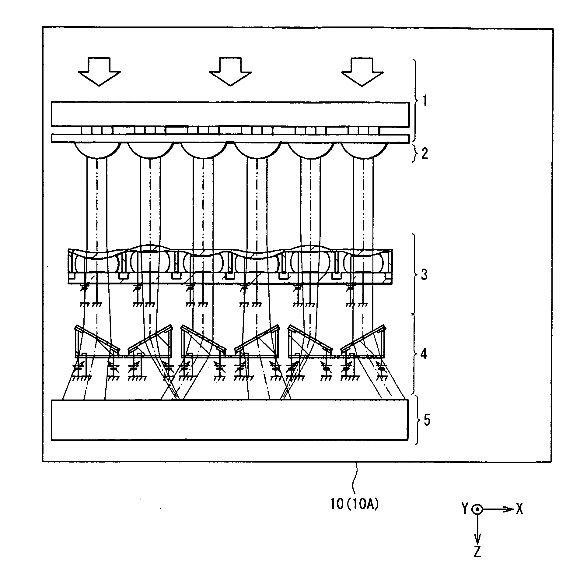
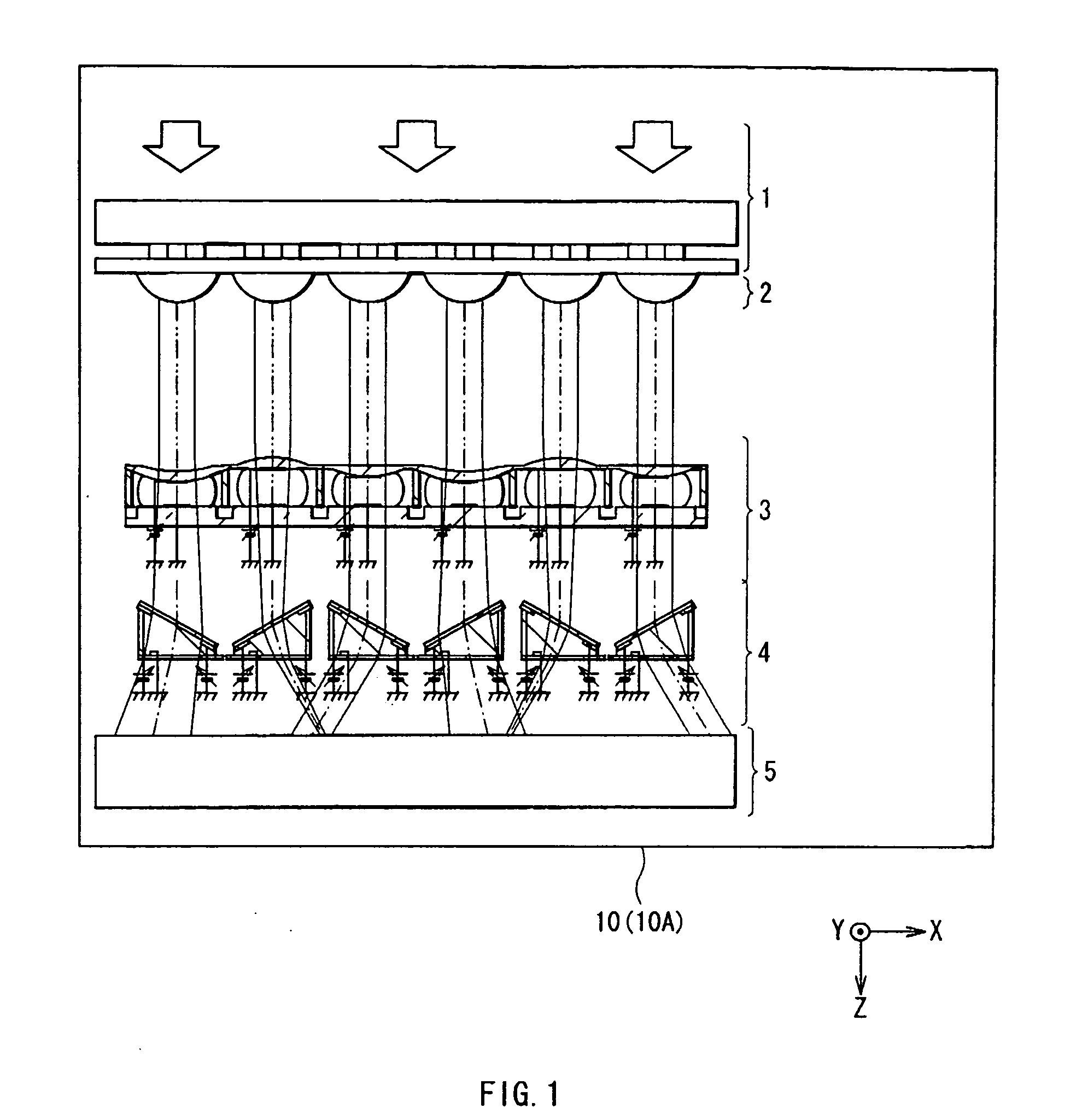
[0048] At first, a three-dimensional display 10 (to distinguish from a second embodiment which will be described later, hereinafter referred to as three-dimensional display 10A) according to a first embodiment of the invention will be described below. FIG. 1 shows a structural example of the three-dimensional display 10A. FIG. 1 is a schematic view in a horizontal plane.

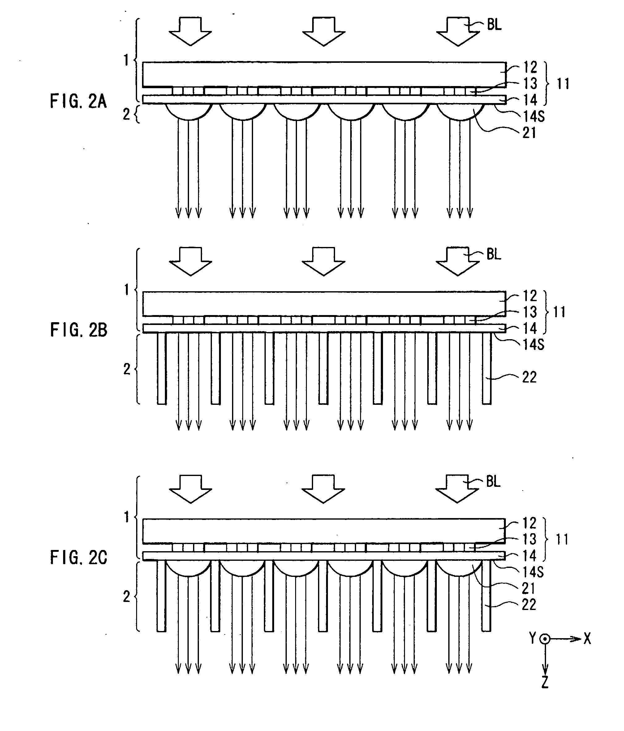
[0049] The three-dimensional display 10A includes a two-dimensional display section 1 having a plurality of pixels, a collimation section 2 converting the wavefront of display image light emitted from each pixel into a parallel light flux, a lens array 3 converting the wavefront of the parallel light flux converted in the collimation section 2 into a wavefront having a curvature which allows the display image light to focus upon a focal point where an optical path length from an observation point to the focal point is equal to an optical path length from the observation point to a virtual object point, a horizontal ...

second embodiment

[0090] Next, a three-dimensional display 10B according to a second embodiment of the invention will be described below. In the first embodiment, the variable focal-length lens is used as a wavefront conversion means. In the embodiment, a variable focal-length mirror is used.

[0091]FIG. 18 is a conceptual diagram for describing the whole structure of the three-dimensional display 10B. As shown in FIG. 18, the three-dimensional display 10B includes the two-dimensional display section 1, the collimation section 2, a mirror array 6 as a wavefront conversion means and a deflecting mirror 4B as a deflection means in order.

[0092] The mirror array 6 includes a plurality of variable focal-length mirrors 61 as shown in FIG. 19. FIG. 19 shows a schematic sectional view of the mirror array 6. As in the case of the variable focal-length lens 31, the variable focal-length mirror 61 is an optical device capable of freely changing its focal length by deforming a part of the variable focal-length m...

example

[0102] Next, an example of the invention will be described below.

[0103] In the example, a variable focal-length lens 31E with a structure shown in FIG. 20 according to the invention was formed, and the characteristics of the variable focal-length lens 31E were evaluated.

[0104] As shown in FIG. 20, in the variable focal-length lens 31E as the example, a transparent deformation member 33E having a thickness gradually reduced from a central position CL and a column 34E were integrally molded. The transparent deformation member 33E had a circular plan shape having its center in the central position CL. Moreover, a space between a transparent electrode layer 36E and a transparent electrode layer 37E which were arranged in a central region in a thickness direction was 0.01 mm. The transparent electrode layers 36E and 37E were made of ITO, and were circular thin films with a diameter of 0.8 mm. A filling layer 35E was made of silicone. The filling layer 35E was formed through coating a d...


PUM


Abstract

In the three-dimensional display, a two-dimensional display section generates a two-dimensional display image based on an image signal, and a lens array converts the wavefront of the display image light from the two-dimensional display section into a wavefront having a curvature which allows the display image light to focus upon a focal point where an optical path length from an observation point to the focal point is equal to an optical path length from the observation point to a virtual object point, so a viewer can obtain information about an appropriate focal length in addition to information about binocular parallax and a convergence angle. Therefore, consistency between the information about binocular parallax and a convergence angle and the information about an appropriate focal length can be ensured, and a desired stereoscopic image can be perceived without physiological discomfort.

Description

CROSS REFERENCES TO RELATED APPLICATIONS [0001] The present invention contains subject matter related to Japanese Patent Application JP 2005-271775 filed in the Japanese Patent Office on Sep. 20, 2005, the entire contents of which being incorporated herein by reference. BACKGROUND OF THE INVENTION [0002] 1. Field of the Invention [0003] The present invention relates to a three-dimensional display which displays a stereoscopic image of an object in space. [0004] 2. Description of the Related Art [0005] Examples of methods of generating a stereoscopic image in related arts include a method of sending different images (parallactic images) to the right eye and the left eye of a viewer wearing glasses with different color lenses, a method of sending parallactic images to the right eye and the left eye of a viewer wearing goggles with liquid crystal shutters while switching the liquid crystal shutters at high speed, and the like. Moreover, there is a method of displaying a stereoscopic im...

Claims


Application Information

Patent Timeline
IPC IPC(8): G03H1/08
CPCG02B3/0006G02B3/0056G02B27/2264G02B27/2214G02B3/0081G02B26/004G02B26/0883G02B30/24G02B30/27
Inventor YAMADA, MASAHIROAOKI, SUNAO
Owner SONY CORP
Why Eureka
Try Eureka