Rotating scan camera

a scanning camera and rotating technology, applied in the field of panoramic image reproduction system, can solve the problems of inability to solve, inability to describe counter-rotation optics, and add significant weight and complexity to the device, so as to improve the resolution of the recorded image, improve the light sensitivity of the recording device, and improve the resolution

Inactive Publication Date: 2006-04-06
IMMERSIVE LICENSING
View PDF25 Cites 128 Cited by
  • Summary
  • Abstract
  • Description
  • Claims
  • Application Information

AI Technical Summary

Benefits of technology

[0015] A. It is an object of the present invention to provide a method, and an apparatus for applying that method, for stereoscopic imaging of a surrounding scene by means of separated views having equal parallax separation throughout the scene.
[0016] B. It is also an object of the present invention to provide a method, and an apparatus for applying that method, for increasing the resolution of the recorded image by the use of multiple line scan sensors. Unlike the prior art, which is directed toward one to two sensors and optical paths, this use of multiple sensors enables better resolution in the final image and the use of sensors that would otherwise be unable to give good results in a single scan.
[0017] C. It is also an object of the present invention to provide a method, and an apparatus for applying that method, for increasing the light sensitivity of the recording device by the storage and addition of redundant scans from line scan sensors, unlike the prior art, which is directed toward a single pass recording of a given subject.
[0018] D. It is also the object of the present invention to provide a method, and an apparatus for applying that method, for recording panoramic images in full motion, by means of a simplified recording mechanism. The prior art is largely directed toward the production of panoramic still photographs, and the art featuring film-based recording in particular is unsuitable for motion picture photography, because of the need to put a large and heavy film transport and storage mechanism into rapid motion.
[0019] E. It is also an object of the present invention to provide means for recording a fully spherical field of view in a seamless manner. The prior art for panoramic scanning is primarily directed toward a cylindrical panoramic format that omits a substantial portion of the surrounding scene, and spherical imaging to date has mainly involved multiple views that must be seamed together prior to viewing, or scanning approaches that produce interruptions in the field of view.
[0020] F. It is also an object of the invention to dynamically adjust the convergence of a panoramic stereoscopic view in order to focus viewing on objects at selected distances. No prior art addresses this problem.

Problems solved by technology

This adds significant weight and complexity to the device, and also requires that a perfectly consistent geometrical relationship be consistently maintained between the input lens and the sensor along a long optical path, even while the whole apparatus is in rapid motion and presumably being carried in the field in the manner of a regular camera.
The described counter-rotation optics are also inherently impractical, because as the overall apparatus rotates, at the point where the lens is opposite the sensor, the mirror surfaces and their optical supports need to completely disappear in order to avoid an interruption in the image.
What these solutions lack is an effective way to record not only the appearance of the real world in motion through the slit, but also to use that information to create a stereoscopic image of the entire field of view.
Without that stereoscopic information, the most realistic picture of a surrounding scene is not possible, as well as other applications such as rangefinding that depend on parallax offsets between different points of view.
In addition, the described method suggests that there would be significant light interference between the light from the two cameras.

Method used


Image

  • Rotating scan camera
  • Rotating scan camera
  • Rotating scan camera

Examples


Embodiment Construction

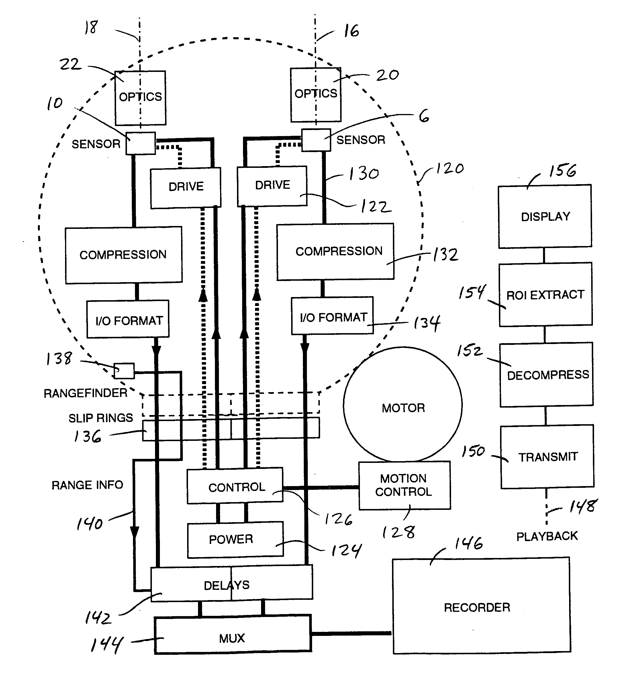
[0036] A rotary scanning camera of a novel design offers improved performance in capturing a panoramic surrounding scene. One or more line-scan sensors are used in a sweeping recording of a surrounding scene. The scan can be of a partial rotation or of one or more full rotations. Unlike most of the prior art, these sensors each have an optical axis that does not intersect the axis of rotation.

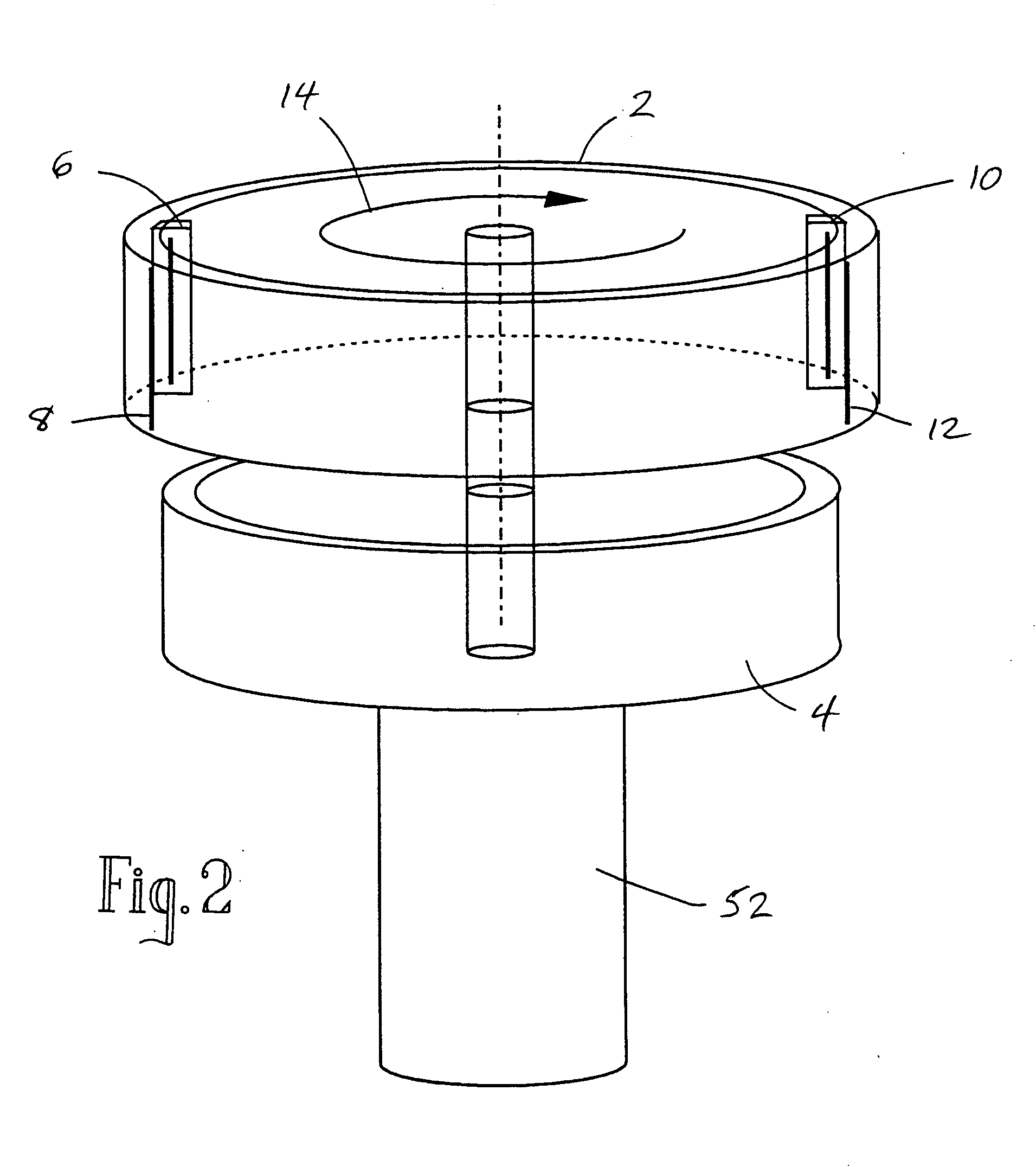
[0037] In the preferred embodiment, a rotating drum holds two or more line-scan devices for scanning the appearance of a surrounding field of view from stereoscopically separated viewpoints, with each optical axis on approximately a tangent line to the cylinder. This creates a pair of offset sweeping scans that record objects in the surrounding view from one, then the other, point of view, thereby creating an effective parallax separation in the recorded images. This parallax separation is the same for every point in the rotation of the drum.

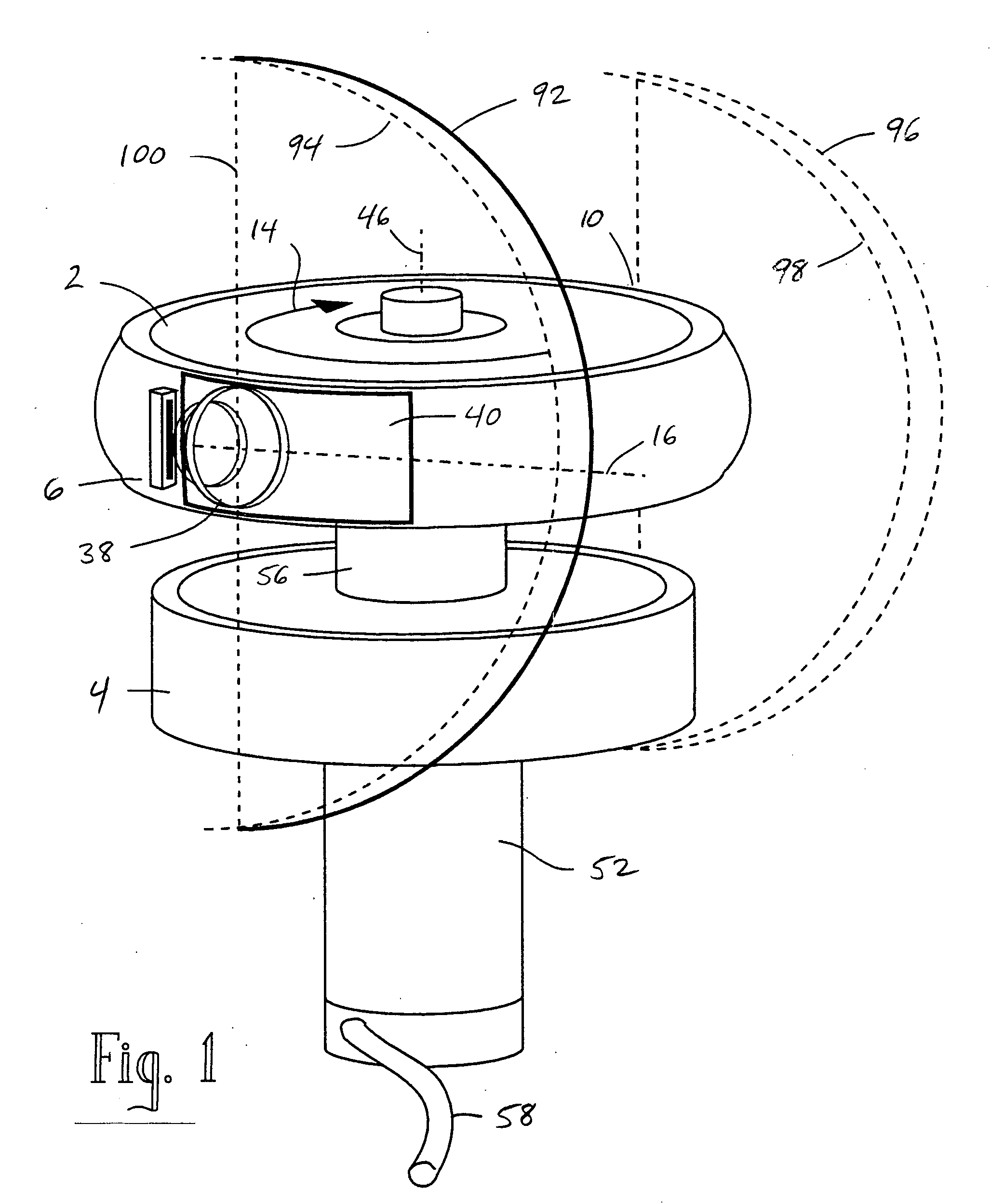
[0038]FIG. 1 shows an oblique view of the preferred...


PUM


Abstract

A scanning camera with a rotating drum has one or more sensors characterized by a non-radial optical axis. With two sensors on opposite sides of the drum and facing in substantially the same direction, stereoscopic recording of a panorama is accomplished as the drum rotates. The adjustment of convergence between stereoscopic viewpoints is described that improves the viewing and interpretation of stereoscopic images. Rapid rotation of the scanning camera produces panoramic motion picture recording, with the final frame speed dependent on the sensitivity and speed of the sensor, the resolution desired, and the capabilities of the recording device. The preferred embodiment employs rotating fisheye lenses for a substantially full-sphere field of view. Additional sensors in the same arrangement are used to increase resolution and light sensitivity through multiplexed or additive recording of the image data. Recording image information using film, either internal or external to the camera drum, is also described as a cost-effective alternative to digital media storage.

Description

BACKGROUND [0001] 1. Field of the Invention [0002] This invention generally relates to a panoramic image reproduction system, and in particular to the use of rotary scanning elements in a camera design, with multiple sensors being used to establish stereoscopic viewpoints, adjust their convergence, and to increase the density of information being scanned. [0003] 2. Description of the Prior Art [0004] Cameras for capturing still or motion pictures of the external world have usually used an area array sensor, such as a 640×480 Charge-Coupled Device (CCD) for NTSC video images. These area sensors use a rectangular or square area of light-sensitive elements and expose them all at once. New forms of Complementary Metal Oxide Semiconductor (CMOS) sensors for cameras are also being made in a variety of resolutions. [0005] Linear scan sensors, either CMOS or CCD, are also being used to increase resolution for specific applications. These sensors have a single row of sensors, designed for mo...

Claims


Application Information

Patent Timeline
Patent Type & Authority Applications(United States)
IPC IPC(8): H04N5/225H04N7/00H04N13/00H04N15/00
CPCG03B17/02G03B19/18G03B35/08G03B37/02H04N5/2251H04N5/23238H04N5/2353H04N5/772H04N13/0055H04N13/0242H04N13/243H04N13/189H04N23/60H04N23/50H04N23/698H04N23/73
Inventor MCCUTCHEN, DAVID JOHNSTONE
Owner IMMERSIVE LICENSING
Why Eureka
Try Eureka