Splicing frame for video wall display units, and video wall

A display unit and video wall technology, applied in rack/frame structure, instruments, identification devices, etc., can solve the problems of reducing the area of ​​the display area and affecting the transparent display effect of the video wall, so as to optimize the splicing structure and improve the display effect. Effect

Active Publication Date: 2014-07-09
BOE TECH GRP CO LTD
View PDF4 Cites 16 Cited by
  • Summary
  • Abstract
  • Description
  • Claims
  • Application Information

AI Technical Summary

Problems solved by technology

like figure 1 As shown, when developing a video wall with a transparent display effect, it is found that after the transparent display unit 200 is spliced ​​through the existing splicing frame 100 ′, the chip-on-film board 210 (Chip On Film, COF for short) and the printed circuit board 220 ( The Printed Circuit Board (PCB f

Method used


Image

  • Splicing frame for video wall display units, and video wall
  • Splicing frame for video wall display units, and video wall
  • Splicing frame for video wall display units, and video wall

Examples


Embodiment Construction

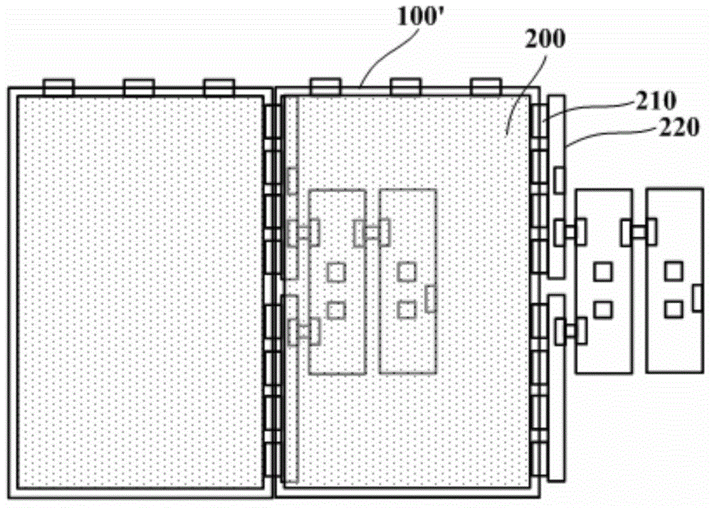
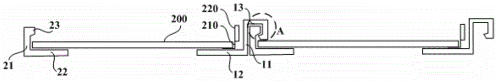
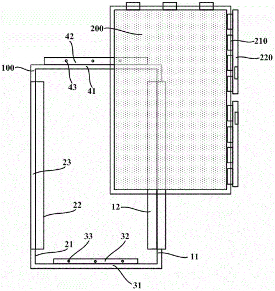
[0031] In order to reduce the area overlap between the chip-on-film board and the printed circuit board and the adjacent display unit, and optimize the splicing structure of the video wall, an embodiment of the present invention provides a splicing frame of the display unit of the video wall and a video wall. In the technical solution of the present invention, the chip-on-chip film board and the printed circuit board of the display unit can be folded between the display unit body and the first side plate, and the chip-on-chip film board and the printed circuit board will not be adjacent to the first splicing direction. The area of ​​the display unit overlaps, which greatly optimizes the splicing structure of the video wall. When the splicing frame is applied to the video wall with a transparent display effect, the chip-on-film board and the printed circuit board are invisible, so compared with the existing technology, it can improve The display effect of the video wall.

[003...


PUM


Abstract

The invention relates to the technical field of display, and discloses a splicing frame for video wall display units, and a video wall. According to the splicing frame and the video wall, area overlapping between adjacent display units and flip chip thin film plates and between adjacent display units and printed circuit boards is reduced, and the splicing structure of the video wall is optimized. The pair of opposite lateral sides of the splicing frame respectively comprise a first side plate, a first limiting bottom plate connected with the first side plate and located inside the first side plate, a clamping groove connected with the first side plate and bent towards the outer side of the first side plate, a second side plate, a second limiting bottom plate connected with the second side plate and located inside the second side plate, a clamping protrusion connected with the second side plate and bent towards the inner side of the second side plate, and two adjacent splicing frame bodies in the first splicing direction, wherein the flip chip thin film plates of the display units and the printed circuit boards can be bent into the portions between display unit bodies and the first side plates, and the clamping protrusion of each splicing frame body can be clamped into the clamping groove of the corresponding splicing frame.

Description

technical field [0001] The invention relates to the field of display technology, in particular to a splicing frame of a video wall display unit and a video wall. Background technique [0002] With the continuous maturity of display technology, large-area display devices are widely used in military, public security, railway, aviation, finance, securities and other fields. The video wall is a computer-based display, playback and control system, including multiple display units that are spliced ​​together. Users can flexibly choose the display mode of the video wall, for example, select a certain group of screens, full screen or custom multi-screen show. [0003] At present, in order to meet the needs of the market, more and more manufacturers are committed to developing video walls with transparent display effects, so as to bring a new interactive experience to users. Such as figure 1 As shown, when developing a video wall with a transparent display effect, it is found that...

Claims


Application Information

Patent Timeline
IPC IPC(8): H05K7/18G09F9/30
Inventor 郑喆奎
Owner BOE TECH GRP CO LTD
Why Eureka
Try Eureka