Description method of lighting source for lithography machine

An illumination light source and lithography machine technology, applied in the field of lithography machines, can solve the problems affecting the speed and quality of the lighting source optimization of the lithography machine, and achieve the effects of reducing the production cycle and time cost, reducing the quantity and increasing the speed.

Active Publication Date: 2016-03-09
BEIJING GUOWANG OPTICAL TECH CO LTD
View PDF3 Cites 0 Cited by
  • Summary
  • Abstract
  • Description
  • Claims
  • Application Information

AI Technical Summary

Problems solved by technology

It can be seen from the above process that the selection of the description method of the lighting source of the lithography machine will affect the sub-processes such as imaging simulation, calculation of the objective function, and iterative update of optimization parameters in the optimization of the lighting source of the lithography machine, thereby affecting the speed and quality of the optimization of the lighting source of the lithography machine

Method used


Image

  • Description method of lighting source for lithography machine
  • Description method of lighting source for lithography machine
  • Description method of lighting source for lithography machine

Examples


Embodiment Construction

[0026] The present invention will be further described below in conjunction with the embodiments and accompanying drawings, but the protection scope of the present invention should not be limited thereby.

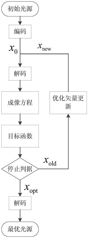
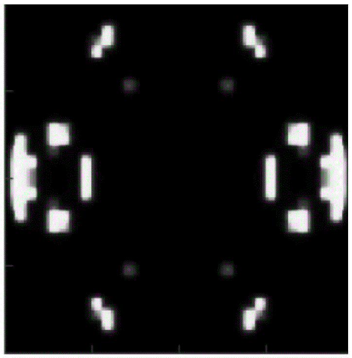
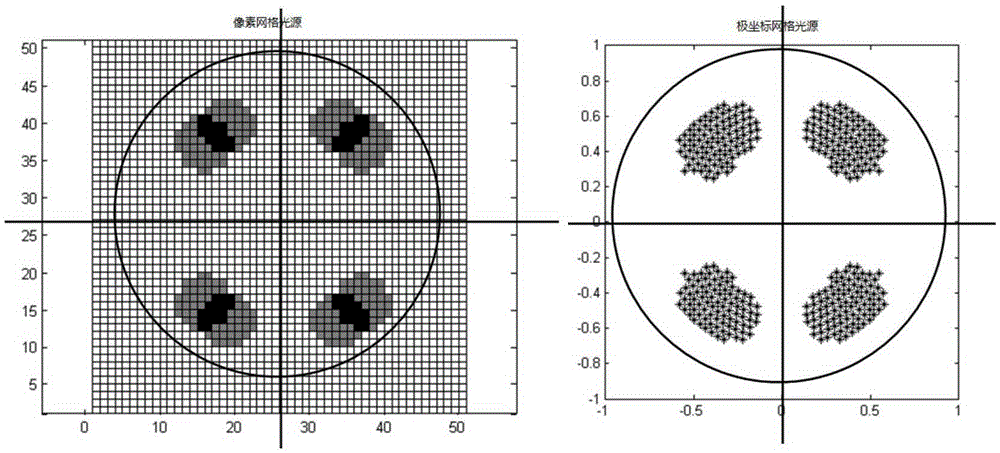
[0027] The method for describing the lighting source of the lithography machine according to the present invention is as follows: Figure 4 shown. Each circular sub-illumination source requires four parameters (r σ ,r,θ,g) description, where r σ is the radius of the sub-illumination light source, (r, θ) is the polar coordinate of the center of the sub-illumination light source, and g is the light intensity of the sub-illumination light source. The photolithography machine illumination light source in the embodiment consists of 20 radius r σ =0.05 of the sub-illumination light source (note: the maximum radius of the illumination source is 1), so the light source of the lithography machine can be described by the following vector,

[0028]

[0029] The total number N o...


PUM


Abstract

The invention discloses a method for describing a lithography machine illuminating light source. The method can be used for describing the lithography machine illuminating light source according to coordinates, light intensity and other parameters of a group of round sub-illuminating light sources which are overlapped with one another. According to the method, the number of variables needed for describing the lithography machine illuminating light source is reduced, and the speed of obtaining an optimal lithography machine illuminating light source is improved.

Description

technical field [0001] The invention relates to a photolithography machine, in particular to a method for describing an illumination light source of a photolithography machine. Background technique [0002] Lithography machine is the most technically difficult and most expensive key equipment in integrated circuit equipment. The lithography machine system includes illumination sources, masks, projection systems, wafers and other sub-systems. Using an optimized illumination source can increase the photolithography process window, making it possible to perform photolithography of smaller feature size patterns. The modern integrated circuit manufacturing process usually includes the following steps. First, use optimization software to optimize the illumination source of the lithography machine according to the target lithography pattern, and then fine-tune and verify the optimal illumination source on the real lithography machine. Fine-tuned and verified optimal illumination ...

Claims


Application Information

Patent Timeline
Patent Type & Authority Patents(China)
IPC IPC(8): G03F7/20
Inventor 杨朝兴王向朝李思坤
Owner BEIJING GUOWANG OPTICAL TECH CO LTD
Why Eureka
Try Eureka