Light dimming circuit suitable for linear high-voltage LED driver

An LED driver and dimming circuit technology, applied in the field of LED lighting, can solve the problems of poor dimming effect and low efficiency, and achieve the effect of solving the poor dimming effect

Active Publication Date: 2014-07-16
SHAANXI REACTOR MICROELECTRONICS
View PDF3 Cites 3 Cited by
  • Summary
  • Abstract
  • Description
  • Claims
  • Application Information

AI Technical Summary

Problems solved by technology

However, compared with LED lamps driven by switching power supplies, there is still room for improvement in the invention of dimming.
[0003] At present, the dimming control of LED lamps using linear high-voltage LED drivers generally uses silicon controlled silicon dimmers, which not only have low efficiency but also poor dimming effects.

Method used


Image

  • Light dimming circuit suitable for linear high-voltage LED driver
  • Light dimming circuit suitable for linear high-voltage LED driver
  • Light dimming circuit suitable for linear high-voltage LED driver

Examples


Embodiment Construction

[0023] In order to make the purpose, technical solutions and advantages of the present invention clearer, the technical solutions in the present invention will be clearly and completely described below in conjunction with the accompanying drawings in the present invention. Obviously, the described embodiments are part of the embodiments of the present invention , but not all examples. Based on the embodiments of the present invention, all other embodiments obtained by persons of ordinary skill in the art without creative efforts fall within the protection scope of the present invention.

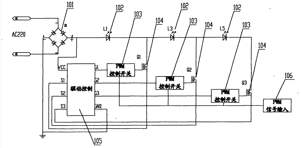
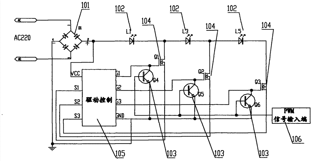
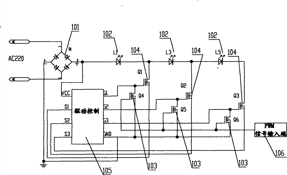
[0024] figure 1 A structural schematic diagram of a dimming circuit suitable for a linear high-voltage LED driver for the present invention, as figure 1 As shown, the positive pole of the rectifier bridge stack 101 is connected to the positive pole of the first LED string 102, the positive pole of the second LED string 102 is connected to the negative pole of the first LED string 102, and th...


PUM


Abstract

The invention provides a light dimming circuit for a linear high-voltage LED driver. The light dimming circuit comprises a bridge rectifier, at least two sections of LED strings, a driving control IC, a driving switch, a PWM control switch and a PWM signal input end, wherein positive electrodes and negative electrodes of the LED strings are in serial connection in an end-to-end mode. After the PWM control switch receives PWM signals, the time proportion of on-off time of the driving switch is controlled to adjust the time ratio between luminous time and nonluminous time of the LED strings to finally achieve the purpose of dimming light. The light dimming circuit achieves the light dimming function of LED lighting lamps by using the linear high-voltage LED driving scheme.

Description

technical field [0001] The invention belongs to the technical field of LED lighting, and in particular relates to a dimming circuit suitable for a linear high-voltage LED driver. Background technique [0002] Now some companies have introduced a linear high-voltage LED driver to drive LED lamps. It needs to connect no less than two LED strings in series or a combination of series and parallel LED strings into the circuit in sequence, and then the rectified pulsation The voltage is applied to the LED string, and finally the voltage input to each segment of the LED string is measured by the drive control chip. After the input voltage reaches a certain value, the driver chip drives the first segment of the LED string and constant current at a lower current value; After reaching a higher voltage, drive the second segment of the LED string and keep the constant current at a higher current; finally wait until the voltage is higher, then switch on the third segment of the LED strin...

Claims


Application Information

Patent Timeline
Patent Type & Authority Applications(China)
IPC IPC(8): H05B37/02
Inventor 杨波杨世红
Owner SHAANXI REACTOR MICROELECTRONICS
Why Eureka
Try Eureka