Novel laser rust removing device

A new type of laser derusting technology, applied in laser welding equipment, welding equipment, metal processing equipment, etc., can solve the problems that the equipment cannot maintain the working posture, flash rust, weak adsorption force, etc., and achieve high commercial promotion and application value, The technical concept is advanced and practical, and the effect of low manufacturing cost

Active Publication Date: 2014-07-23
ZHEJIANG OCEAN UNIV
View PDF7 Cites 7 Cited by
  • Summary
  • Abstract
  • Description
  • Claims
  • Application Information

AI Technical Summary

Problems solved by technology

[0002] At present, most of the devices used for ship maintenance and derusting work adopt permanent magnet crawler adsorption technology. Most of these devices have rigid crawler structures, and it is difficult to achieve frequent curvature changes during movement, and the attachment surface to the hull surface is small. Adsorption The force is not strong, and the traditional derusting device mostly adopts high-pressure water spray derusting method, so there are three problems: First, the effective contact area between the crawler and the hull surface is reduced when passing through the surface of the hull with a large curvature. Fore and stern, bilge and other parts with large curved surfaces, the track or driving wheel of the device cannot reach the minimum value of the effective bonding area required for normal work with the surface of the hull, thus reducing the adsorption force, causing the entire device to not move normally, or even A fall accident occurred; second, due to its relatively fixed track and internal structure, the equipment carried by the device cannot maintain a good working posture on the surface of the hull with different curvatures and large changes, which affects the quality of work
The third is that the high-pressure water spray derusting technology will produce flash rust during the derusting operation, and it cannot produce roughness, which has many limitations in actual operation

Method used


Image

  • Novel laser rust removing device
  • Novel laser rust removing device
  • Novel laser rust removing device

Examples


Embodiment Construction

[0018] The technical solutions of the present invention will be further described below with reference to the accompanying drawings.

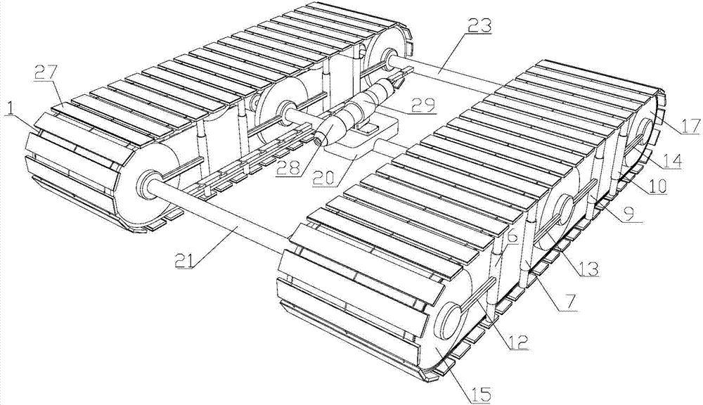
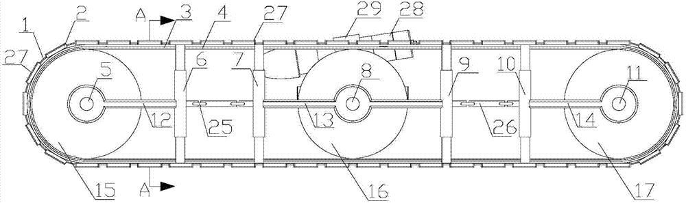
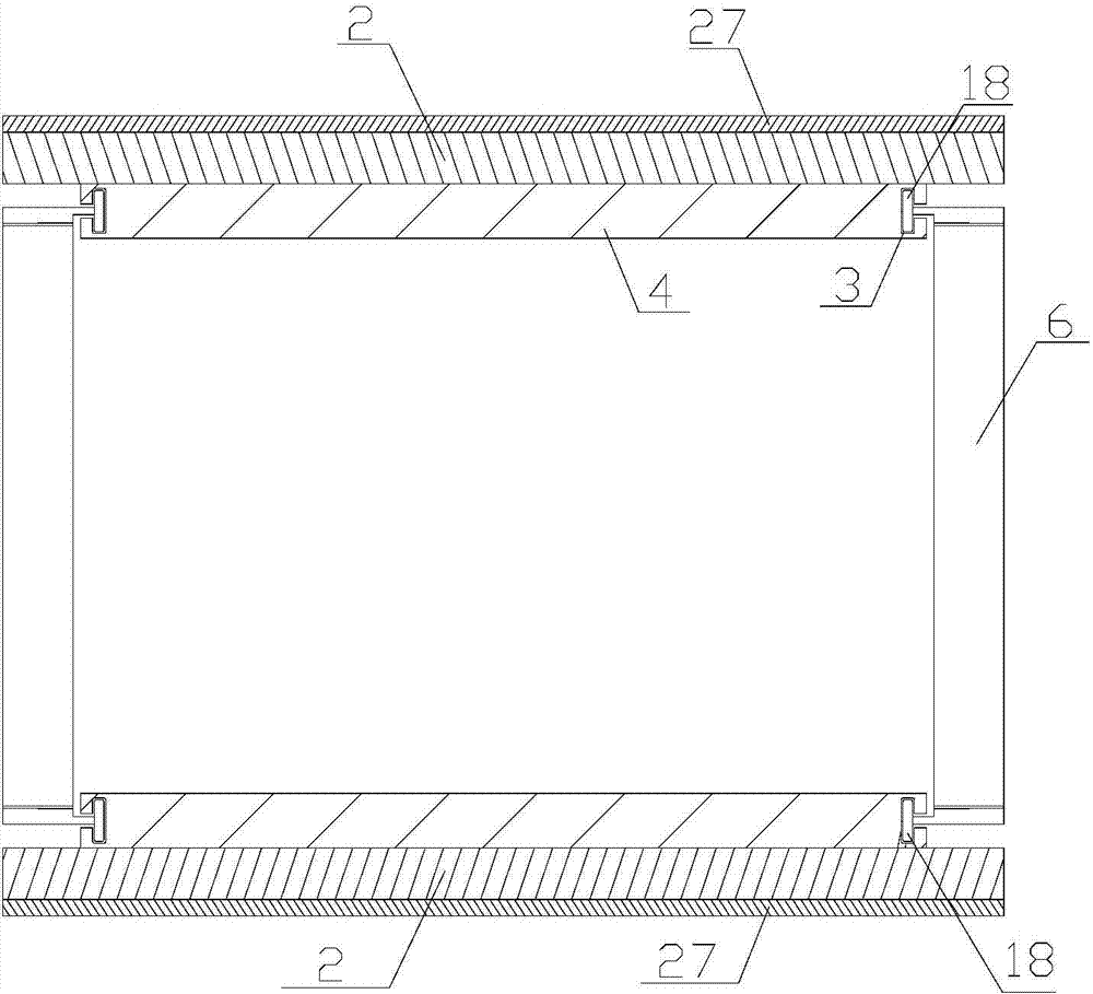
[0019] As shown in the figure, a new type of laser descaling device includes a laser descaling device 28 and a hull climbing wall mounting platform on which the laser descaling device 28 is placed. The hull climbing wall mounting platform includes two magnetic drive units , four sets of belt tension adjustment mechanisms, head beam 21, middle beam 22, tail beam 23, four flexible longitudinals 19 and an equipment carrying base 20, wherein the magnetic drive unit includes a head motor 5, a middle motor 8, a tail motor 11, The first driving wheel 15, the secondary driving wheel 16, the tail driving wheel 17, the track connecting hinge 1, the permanent magnet 2 and the transmission belt 4; Rod 7, middle and rear hydraulic telescopic link 9, tail hydraulic telescopic link 10, hydraulic telescopic link pulley 18, head hydraulic link bracket 12, middl...


PUM


Abstract

The invention discloses a novel laser rust removing device. The novel laser rust removing device comprises a laser rust remover and a hull wall-climbing carrying platform where the laser rust remover is placed. The hull wall-climbing carrying platform comprises two magnetic drive units, four belt tightness regulating mechanisms, a head cross beam, a middle cross beam, a tail cross beam, four flexible longitudinal ribs and an equipment carrying base. Through matching between the four flexible longitudinal ribs and the four belt tightness regulating mechanisms, the novel laser rust removing device can stretch, contract and bend freely within certain limits so as to be attached to the surface of a hull, and the equipment carrying base can be kept in the balanced posture. Thus, the laser rust remover can carry out the rust removing work in the steady posture and complete the hull rust removing work efficiently.

Description

technical field [0001] The invention relates to a laser rust removal device, in particular to a laser rust removal device for hull climbing walls of a flexible skeleton. Background technique [0002] At present, most of the devices used for ship maintenance and derusting operations use permanent magnet crawler adsorption technology. Most of these devices have rigid crawler structures and are difficult to achieve frequent curvature changes during movement. The force is not strong, and the traditional rust removal devices mostly use high-pressure water spray to remove rust, so there are three problems: First, when passing through the hull surface with large curvature, the effective contact area between the crawler and the hull surface is reduced, such as ships. For some parts with large curved surfaces such as the fore and aft parts, the bilge part, the track or driving wheel of the device cannot reach the minimum effective contact area required for normal operation with the s...

Claims


Application Information

Patent Timeline
Patent Type & Authority Applications(China)
IPC IPC(8): B23K26/36B23K26/70
CPCB23K26/36B23K26/702
Inventor 王化明邬宾杰陈春萍
Owner ZHEJIANG OCEAN UNIV
Why Eureka
Try Eureka