Pipe joint assembly and transportation equipment

A technology of special equipment and components, applied in the direction of pipes/pipe joints/fittings, mechanical equipment, pipes, etc., can solve the problems of increased construction difficulty, decreased installation stability, and increased difficulty, so as to simplify the installation process and improve reliability. performance, a wide range of applications

Inactive Publication Date: 2014-07-23
陈瑾
View PDF5 Cites 2 Cited by
  • Summary
  • Abstract
  • Description
  • Claims
  • Application Information

AI Technical Summary

Problems solved by technology

[0004] However, the whole special equipment is placed on the ground through the installation bracket. If the installation position on the transportation pipeline is too high, the installation bracket must have a corresponding height. Detachment, leading to safety accidents; when the special equipment is fastened to the transportation pipeline through pipe clamps, if the diameter of the transportation pipeline is too large, the size of the pipe clamp will increase accordingly, and multiple people are required to participate in the installation and construction at the same time, making the construction more difficult; When fixed on the transportation pipeline by fasteners such as bolts, the transportation pipeline needs to be disassembled to install special equipment. After the installation is completed, the transportation pipeline will be re-welded to affect the entire transportation pipeline circuit, which will affect the sealing of the pipeline and the installation and construction are more complicated and difficult. increase, especially when the installation position is too high or the pipe size is too large, hoisting equipment is required
Therefore, it is difficult to install special equipment on the transportation pipeline in the prior art, and the scope of application is limited

Method used


Image

  • Pipe joint assembly and transportation equipment
  • Pipe joint assembly and transportation equipment
  • Pipe joint assembly and transportation equipment

Examples


Embodiment Construction

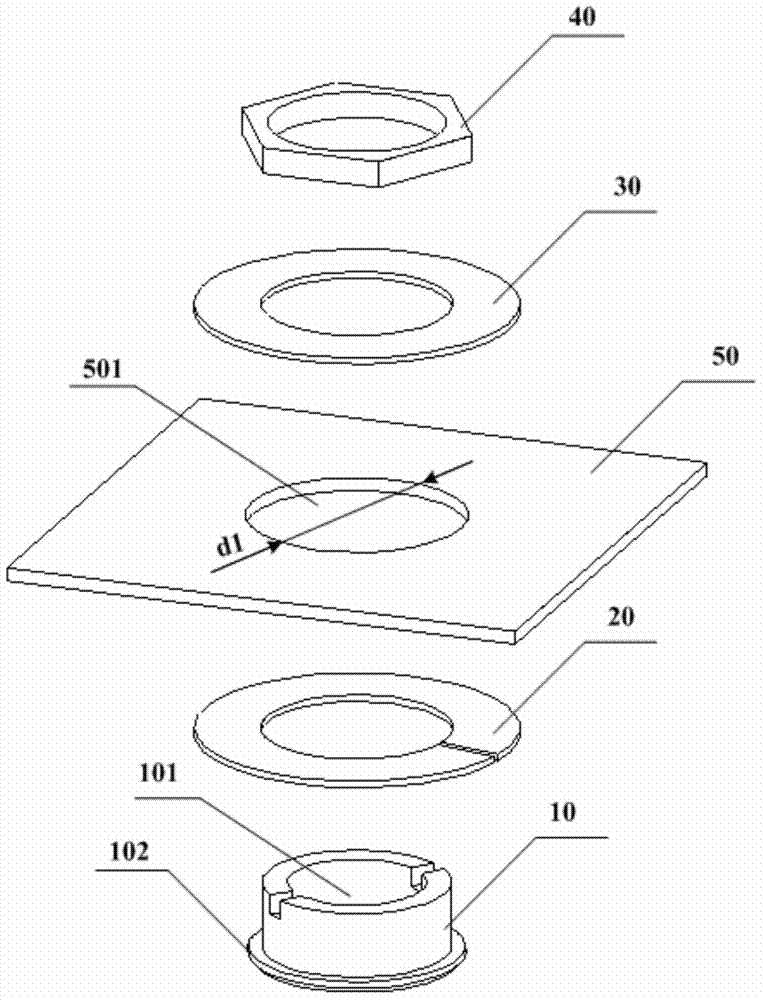
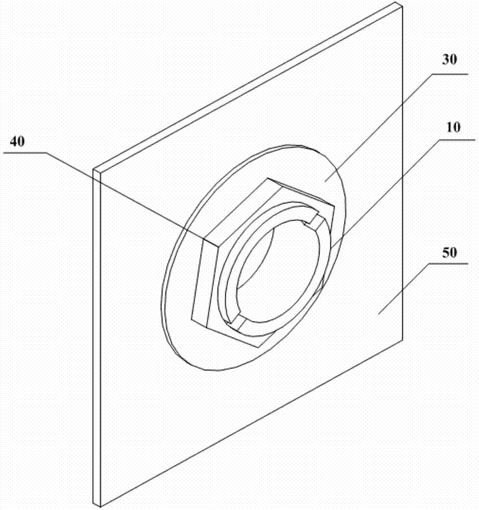
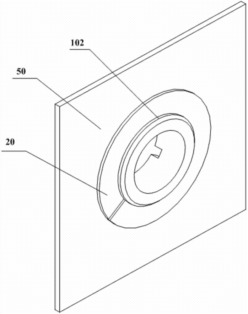
[0035] The purpose of the present invention is to provide a pipe joint assembly and a transportation equipment, which can simplify the installation process of special equipment on the pipeline, make the application scope of the pipe joint assembly wider, and improve the reliability of installation. When the pipe joint assembly provided by the embodiment of the present invention is applied to transportation equipment, since the outer side of the pipe joint has a stepped surface, one end of the pipe joint is penetrated through the opening of the pipe wall, and the inner pressure piece is located between the stepped surface and the inner wall of the pipe wall. During the time, the outer pressure piece is located on the outside of the pipe wall. By tightening the fasteners, the inner pressure piece and the outer pressure piece located on both sides of the pipe wall clamp the pipe wall, so that the pipe joint assembly is reliably fixed on the pipe wall. Special equipment is connecte...


PUM


Abstract

The invention relates to the technical field of transportation equipment, in particular to a pipe joint assembly and a set of transportation equipment. The pipe joint assembly comprises a pipe joint with a through hole, an inner press piece, an outer press piece and a fastener, wherein the inner press piece, the outer press piece and the fastener are arranged on the pipe joint in a sleeved mode. A trapezoidal face is arranged on the outer side face of the pipe joint, and one end of the pipe joint penetrates through an opening of a pipeline wall. The inner press piece is located between the trapezoidal face and the inner wall of the pipeline wall. The outer press piece is located on the outer side of the pipeline wall. The fastener is connected with the pipe joint through threads, and the inner press piece and the outer press piece are made to clamp the pipeline wall. According to the pipe joint assembly, by screwing down the fastener, the inner press piece and the outer press piece located on the two sides of the pipeline wall respectively can be made to clamp the pipeline wall, a set of special equipment can be further connected with the pipe joint of the pipe joint assembly, and therefore, the process of installing the special equipment on a pipeline can be simplified through the pipe joint assembly, the application range of the pipe joint assembly can be wider, and the installing reliability is improved.

Description

technical field [0001] The present invention relates to the technical field of transportation equipment, in particular to a pipe joint assembly and a transportation equipment. Background technique [0002] At present, materials and wastes are often transported by pipelines in various production and manufacturing links. In order to accurately know the information such as the flow status of materials flowing inside the pipelines, special equipment (such as monitoring equipment and fire fighting equipment) is usually installed for detection, detection, and fire extinguishing. And so on, play the role of safety protection. [0003] When installing special equipment on a transportation pipeline, the actuators of the special equipment (such as cameras and nozzles) are usually inserted into the openings of the pipeline wall. It is fastened to the transportation pipeline, or fixed to the transportation pipeline with fasteners such as bolts. [0004] However, the special equipment ...

Claims


Application Information

Patent Timeline
Patent Type & Authority Applications(China)
IPC IPC(8): F16L21/00B25B27/00
CPCF16L41/14
Inventor 程琰吴家栋
Owner 陈瑾
Why Eureka
Try Eureka