A pipe joint device based on mold hydraulic clamping system

A technology of hydraulic clamping and pipe joints, applied in the direction of hose connection device, pipe/pipe joint/pipe fitting, mechanical equipment, etc. and other problems, to achieve the effect of convenient disassembly, improved work performance, reliable connection and no leakage

Inactive Publication Date: 2016-09-28
HEFEI UNIV OF TECH
View PDF5 Cites 0 Cited by
  • Summary
  • Abstract
  • Description
  • Claims
  • Application Information

AI Technical Summary

Problems solved by technology

[0002] At present, the commonly used connection method of the pipe joint body is to directly put the hose on the joint body. After the hydraulic system has been working for a long time, the connection between the hose and the joint body will loosen, which will affect the sealing of the hydraulic system and cause oil leakage. Reduce the oil pressure of the system and affect the working performance of the clamping system

Method used


Image

  • A pipe joint device based on mold hydraulic clamping system
  • A pipe joint device based on mold hydraulic clamping system
  • A pipe joint device based on mold hydraulic clamping system

Examples


Embodiment Construction

[0016] The preferred implementation of the pipe joint device based on the mold hydraulic clamping system of the present invention will be described in detail below with reference to the accompanying drawings.

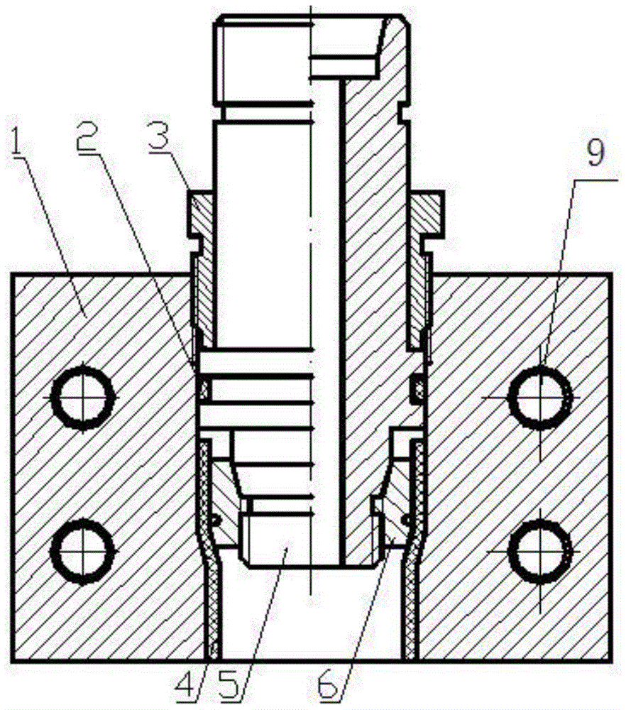
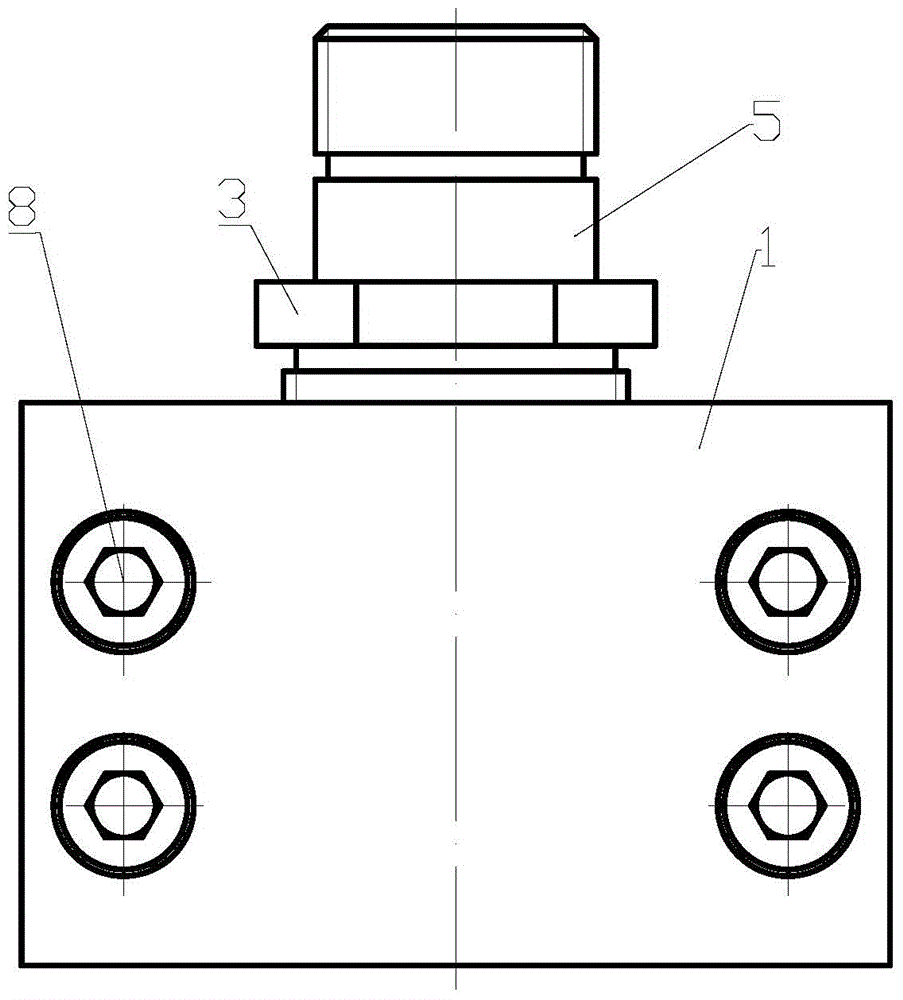
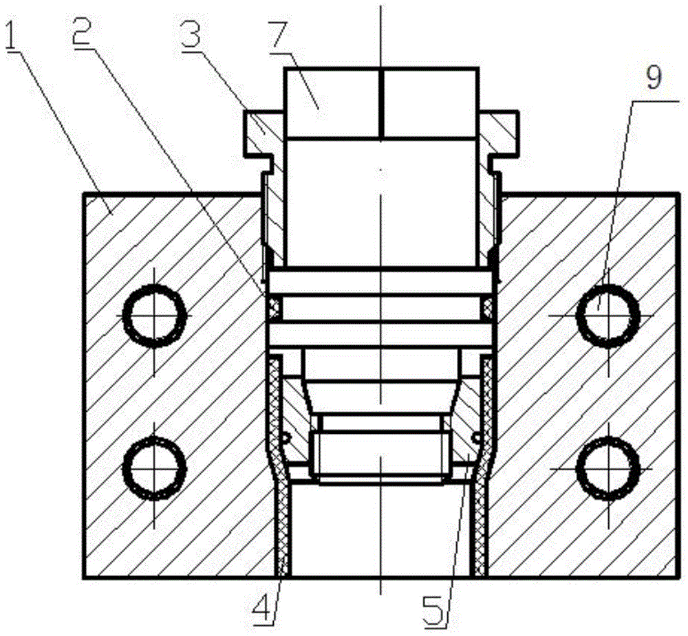
[0017] figure 1 and figure 2 Show the specific implementation of the pipe joint device based on the mold hydraulic clamping system of the present invention: the oil inlet end pressure plate 1 fixes the oil inlet end of the pressure-resistant hose 4, and connects the pipe joint body 5 to provide hydraulic oil for the device. The joint body 5 device includes a pressure plate 1, a joint body 5 body, a pressure-resistant hose 4 and a screw sleeve 3. The pressure plate 1 is provided with a connecting through hole, and the pressure-resistant hose 4 is fixed on the inner side wall of the connecting through hole. The joint body 5 is arranged in the connection through hole. One end of the joint body 5 arranged in the connection through hole is connected with the pressure-resis...


PUM


Abstract

The invention discloses a pipe connector device based on a die hydraulic clamping system. The pipe connector device comprises a pressing plate, a connector body, a pressure hose and an ejecting nut. The pressing plate is provided with a connecting through hole. The pressure hose is fixed on the inner side wall of the connecting through hole. The connector body is arranged at one end inside the connecting through hole and connected with the pressure hose, and the end, located on the outer side of the pressing plate, of the connector body is connected with an external hydraulic pipe and sleeved with the ejecting nut. The ejecting nut is in threaded connection with the connecting through hole. The outer side wall of the connector body is perpendicular to the axis of the connector body and is provided with a check ring. The ejecting nut is in contact with the check ring. Sealing performance of the hydraulic system and tightness of connector connection can be effectively guaranteed, connector connection is reliable, no leakage exists, the oil pressure of the system can be stabilized, and the working performance of the clamping system can be improved.

Description

technical field [0001] The invention relates to a mold hydraulic clamping system on a bending machine, in particular to a pipe joint device based on the mold hydraulic clamping system. Background technique [0002] At present, the commonly used connection method of the pipe joint body is to directly put the hose on the joint body. After the hydraulic system has been working for a long time, the connection between the hose and the joint body will loosen, which will affect the sealing of the hydraulic system and cause oil leakage. Reduce the oil pressure of the system and affect the working performance of the clamping system. Contents of the invention [0003] The technical problem to be solved by the present invention is to provide a pipe joint device based on a mold hydraulic clamping system to increase the tightness between the joint body and the pressure-resistant hose, so as to solve the above-mentioned defects in the prior art. [0004] In order to achieve the above o...

Claims


Application Information

Patent Timeline
Patent Type & Authority Patents(China)
IPC IPC(8): F16L33/22
CPCF16L33/222
Inventor 王勇赵韩张国防王广官尹媛媛胡忠仲
Owner HEFEI UNIV OF TECH
Why Eureka
Try Eureka