Turbofan engine inlet part ice ball collision device

A turbofan and engine technology, which is applied in gas turbine engine testing, jet engine testing, etc., can solve the problem of not giving simulated ice cubes or birds hitting turbofan engines, and achieves easy implementation, high reliability, and simple structure. Effect

Inactive Publication Date: 2014-07-23
SHANGHAI JIAO TONG UNIV
View PDF6 Cites 6 Cited by
  • Summary
  • Abstract
  • Description
  • Claims
  • Application Information

AI Technical Summary

Problems solved by technology

[0004] After searching the existing technology, the patent application number is 200710177013.6, which is named as an invention patent of a turbofan engine and its design method. It proposes a design method of a new turbofan engine, but it does not give simulated ice or Device for bird strikes on turbofan engines

Method used


Image

  • Turbofan engine inlet part ice ball collision device
  • Turbofan engine inlet part ice ball collision device
  • Turbofan engine inlet part ice ball collision device

Examples


Embodiment

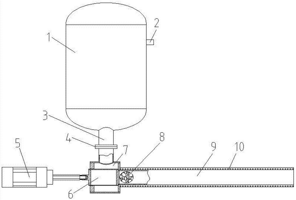
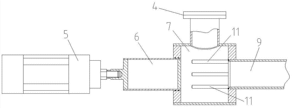
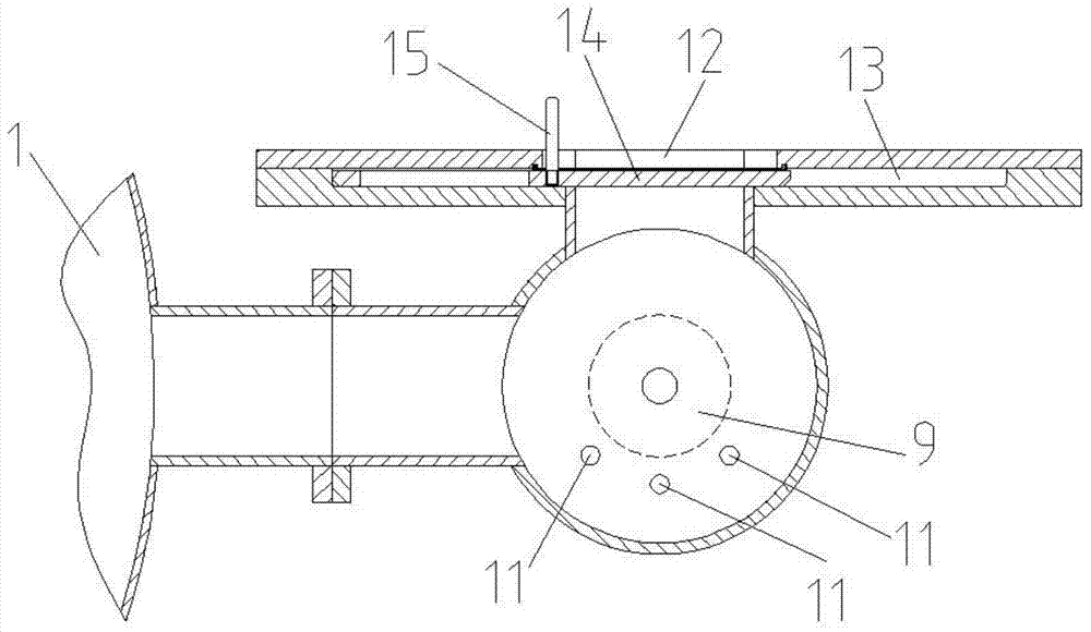
[0019] Examples of the present invention are Figure 1 to Figure 4 As shown, the present invention includes a high-pressure gas storage tank 1, a high-pressure gas inlet pipe 2, a high-pressure gas outlet pipe 3, a flange 4, a locking cylinder 5, a sliding valve in a cabin 6, an ice bomb filling launching cabin 7, an ice bomb 8, Ice bomb launch tube 9, heat insulation material 10, ice bomb support rod 11, ice bomb inlet 12, sliding valve groove 13, ice bomb inlet sliding valve 14 and handle 15, air outlet of high-pressure gas inlet pipe 2, high-pressure gas outlet pipe The air inlets of 3 are all connected with the high-pressure gas storage tank 1, the air inlet of the high-pressure gas inlet pipe 2 is connected with the air outlet of the compressor, and the air outlet of the high-pressure gas outlet pipe 3 fills the launch chamber with the ice bomb through the flange 4 The air inlets of 7 are connected together, the entrance of the ice bomb launching tube 9 is connected with ...


PUM


Abstract

The invention discloses a turbofan engine inlet part ice ball collision device and belongs to the technical field of aeronautical facilities. The device comprises a gas storage tank, a locking air cylinder, a cabin inner sliding valve, an ice ball filling emitting cabin, an ice ball emitting pipe, an ice ball supporting rod, an ice ball inlet, a sliding valve groove, an ice ball inlet sliding valve and a handle. An inlet of the ice ball emitting pipe is connected with the ice ball filling emitting cabin. The cabin inner sliding valve and the ice ball supporting rod are arranged in the ice ball filling emitting cabin. The locking air cylinder is arranged outside the ice ball filling emitting cabin and is connected with the cabin inner sliding valve. The ice ball inlet and the sliding valve groove are formed in the same side wall of the ice ball filling emitting cabin. The ice ball inlet sliding valve is arranged in the sliding valve groove. The handle and the ice ball inlet sliding valve are fixedly connected together. Impact force on ice balls is generated by controlling high-pressure gas, so that the ice balls fly to a target at high speed, and the effect of ice ball collision is achieved. The testing device is simple, parts can be easily purchased or machined, the whole device is easy to implement, and cost is low.

Description

technical field [0001] The invention belongs to the technical field of aviation equipment, and specifically relates to an ice bomb impact device for an inlet part of a turbofan engine that generates impact force on an ice bomb by controlling high-pressure gas, thereby causing the ice bomb to quickly fly to a target. Background technique [0002] The full name of the turbofan engine is a turbofan engine, which is a type of aircraft engine developed from a turbojet engine. Compared with the turbojet, the main feature is that the area of ​​the first stage compressor is much larger, and it is also used as an air propeller, pushing part of the sucked air back through the periphery of the jet engine. The part through which the air of the core part of the engine passes is called the inner duct, and the outer part of the core engine through which only the fan air passes is called the outer duct. Turbofan engines are most suitable for use at a flight speed of 400 to 1,000 kilometers...

Claims


Application Information

Patent Timeline
Patent Type & Authority Applications(China)
IPC IPC(8): G01M15/14
Inventor 董威雷桂林朱剑鋆郑梅
Owner SHANGHAI JIAO TONG UNIV
Why Eureka
Try Eureka