Image stitching method and device
An image stitching and field of view technology, applied in image analysis, image data processing, instruments, etc., can solve the problems of inaccurate reference field of view and low image quality, and achieve the effect of small cumulative deformation and improved image quality.
- Summary
- Abstract
- Description
- Claims
- Application Information
AI Technical Summary
Problems solved by technology
Method used
Image

Examples
Embodiment 1
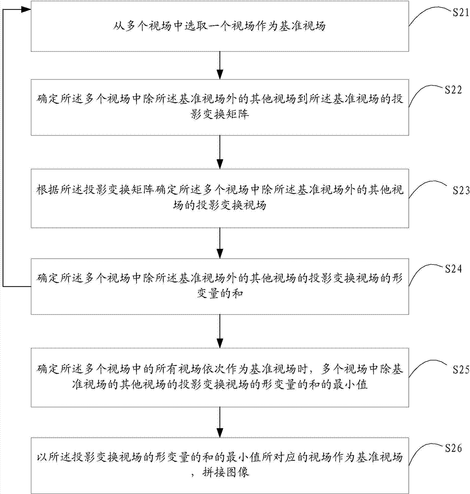
[0035] figure 2 A flow chart of an image mosaic method provided by the first embodiment of the present invention is shown, and the details are as follows:
[0036] Step S21, selecting a field of view from the plurality of fields of view as a reference field of view.
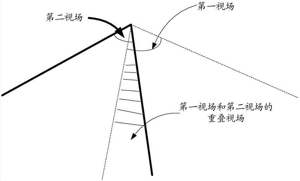
[0037] In this step, multiple cameras shoot multiple fields of view from different angles, and any two adjacent fields of view have a certain overlapping area, so that the fields of view captured by any two cameras can transition through the overlapping area. Randomly select one field of view from the multiple fields of view captured as the reference field of view.
[0038] Step S22 , determining projection transformation matrices from other viewing fields in the multiple viewing fields except the reference viewing field to the reference viewing field.
[0039] In this step, when a reference field of view is selected, other fields of view are projected and transformed into the reference coordinate system where...
Embodiment 2
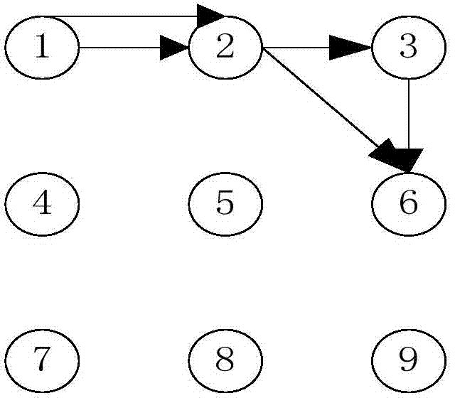
[0090] The following specifically introduces how to determine the shortest path from the field of view projected to the reference field of view. In this embodiment, each field of view is abstracted as a node, which is described in detail as follows:
[0091] First create three tables, namely HIGHER table, TEMP table and LOWER table. The HIGHER table saves the determined nodes and is initially empty; the LOWER table saves undetermined nodes and initially contains all m nodes; the TEMP table is a temporary table. Initially empty.
[0092] The algorithm flow is:
[0093] Step 1: Assuming that the node Vs is selected as the source node, remove it from the LOWER table and put it into the HIGHER table;
[0094] Step 2: Traverse each node in the HIGHER table, for any node V i ∈ HIGHER table, in the LOWER table find the node V i All adjacent nodes, first calculate the relationship between these nodes and V i The projection transformation matrix between, on this basis, calculate th...
Embodiment 3
[0104] Figure 9 A structural diagram of an image stitching device provided by the third embodiment of the present invention is shown, and for convenience of description, only parts related to the embodiment of the present invention are shown. The image stitching device corresponds to the image stitching method of the above-mentioned embodiment.
[0105] In this embodiment, the image stitching device includes: field of view selection unit 91, projection transformation matrix determination unit 92, projection transformation field of view determination unit 93, first deformation amount determination unit 94, second deformation amount determination unit 95, image stitching Unit 96. in:
[0106] The field of view selection unit 91 is configured to select one field of view from a plurality of fields of view as a reference field of view.
[0107] A projection transformation matrix determining unit 92, configured to determine projection transformation matrices from other fields of...
PUM
 Abstract
Description
Claims
Application Information
PatSnap Eureka turns technology decisions into work you can execute. Powered by our Innovation Knowledge Graph, it runs expert workflows across engineering, life sciences, materials and intellectual property. Get your review-ready output in minutes.


