

Supply and exhaust ventilation device
A ventilation device, supply and exhaust technology, applied in the direction of climate sustainability, ventilation system, heating method, etc., can solve the problems of uneven air volume balance, insufficient air volume, and excessive air volume.
- Summary
- Abstract
- Description
- Claims
- Application Information
AI Technical Summary
Problems solved by technology
Method used
Image

Examples
Embodiment approach 1
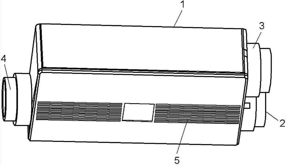
[0044] figure 1 It is a bottom perspective view of the supply and exhaust type ventilator according to Embodiment 1 of the present invention. Such as figure 1 As shown, the air supply and exhaust ventilation device 1 is in the shape of a box, including an indoor air intake 5 , an external air intake 2 , an indoor air exhaust 3 and an external air supply 4 . Here, the indoor air intake port 5 is provided at the lower portion of the supply and discharge type ventilator 1 . The external air suction port 2 and the indoor air exhaust port 3 are arranged on the side of the air supply and discharge type ventilation device 1 . The outside air supply port 4 is provided on the side opposite to the side where the outside air suction port 2 and the indoor air discharge port 3 are provided.
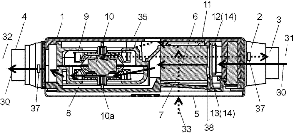
[0045] figure 2 It is a side cross-sectional view of the supply and exhaust type ventilator according to Embodiment 1 of the present invention. Such as figure 2 As shown, the main body 35 of...
Embodiment approach 2
[0072] Figure 11A It is a side view of the supply and discharge type ventilator according to Embodiment 2 of the present invention, Figure 11B It is the bottom view of the air supply and discharge type ventilation device. The supply and exhaust type ventilator 101 according to Embodiment 2 of the present invention is installed on the ceiling, the backside of the ceiling, the space inside the roof, and the side walls in the building. In Embodiment 2 of this invention, the case where it installs in the back of a ceiling is demonstrated.
[0073] Figure 11A The main body 102 shown has the shape of a rectangular parallelepiped that is the lowest in the height direction within three sides. The main body 102 is provided parallel to the ceiling surface 103 . Additionally, if Figure 11B As shown, the main body 102 has an outdoor side suction port 105 and an outdoor side discharge port 106 on one side surface 104 including the height direction and the side in the short side di...
Embodiment approach 3
[0125] In Embodiment 3 of the present invention, the same reference numerals are attached to the same constituent elements as in Embodiment 2, and detailed description thereof will be omitted, and only different points will be described. As described above, in Embodiment 2, the adjustment of the angle of the damper in order to realize the target air volume with high precision has been described. However, air leaks from the exhaust air duct 115 to the air supply air duct 114, and the air volume of the air supply air duct 114 is added to the air volume due to the leakage, and the air volume that can be supplied from the outside becomes insufficient.
[0126] It is considered that the cause of the leakage of air is due to the manufacturing deviation of the supply and discharge type ventilator 101, for example Figure 11A , Figure 11B The shown gaps at the joints of the main body 102 and the partition plate 116 are caused by joint deviations between elements of the heat exchange...
PUM
 Abstract
Description
Claims
Application Information