Pneumatic demolding injection molding mold for thermos bottle caps

A technology of injection mold and pneumatic demoulding, which is applied in the field of molds, can solve the problems of low efficiency and achieve the effect of improving production efficiency

Inactive Publication Date: 2014-07-30
蚌埠市万达塑料制品有限公司
View PDF2 Cites 16 Cited by
  • Summary
  • Abstract
  • Description
  • Claims
  • Application Information

AI Technical Summary

Problems solved by technology

[0002] As is known, the production and processing of thermos bottle caps generally heat the plastic through an injection molding machine, and then inject the molten plastic into the cavity of the injection mold after plasticization. The injection molding process can be roughly divided into the following six stages: "mold closing- Injection-holding-pressure-cooling-opening-product take-out"; the current thermos bottle cap injection mold generally includes a fixed mold and a moving mold, wherein the moving mold includes mold legs, top plate, thimble, water separating plate, core fixing plate, pusher Plate and core, after the mold is opened, the top plate in the movable mold drives the thimble to push the push plate to push out the thermos bottle cap on the core, but for the needs of injection mold closing, the stroke of the thimble is much smaller than that of the thermos bottle Due to the length of the cap, the thermos bottle cap cannot be completely pushed out of the core, and the thermos bottle cap can only be removed manually, which is extremely inefficient

Method used


Image

  • Pneumatic demolding injection molding mold for thermos bottle caps
  • Pneumatic demolding injection molding mold for thermos bottle caps

Examples


Embodiment Construction

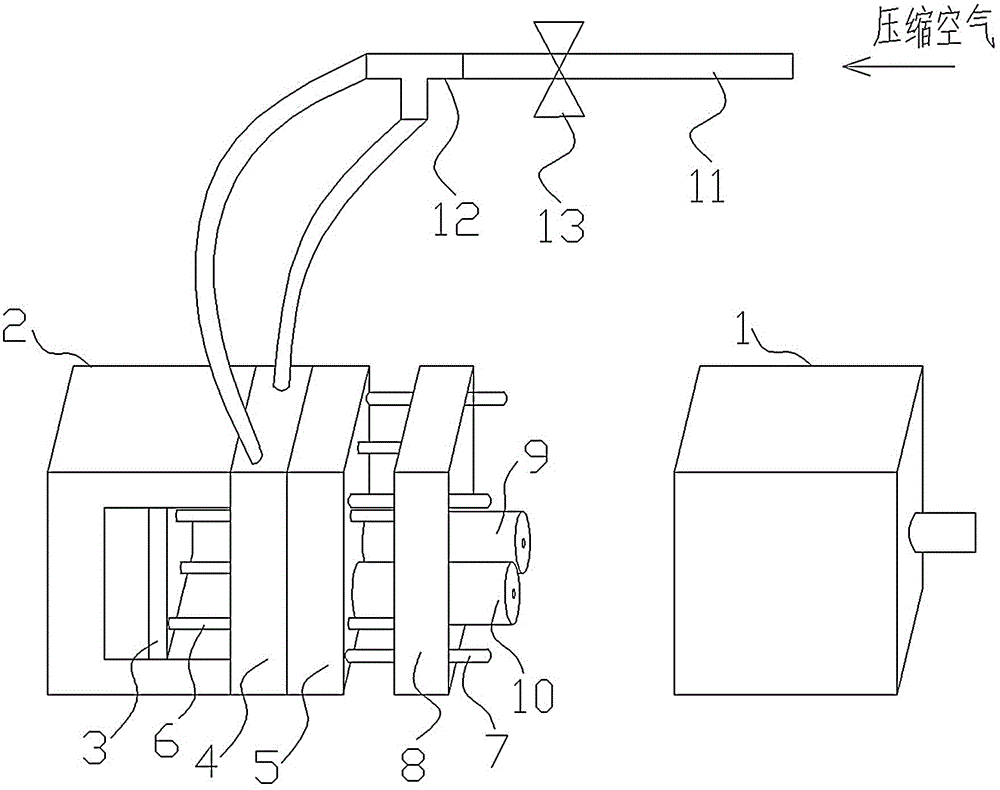
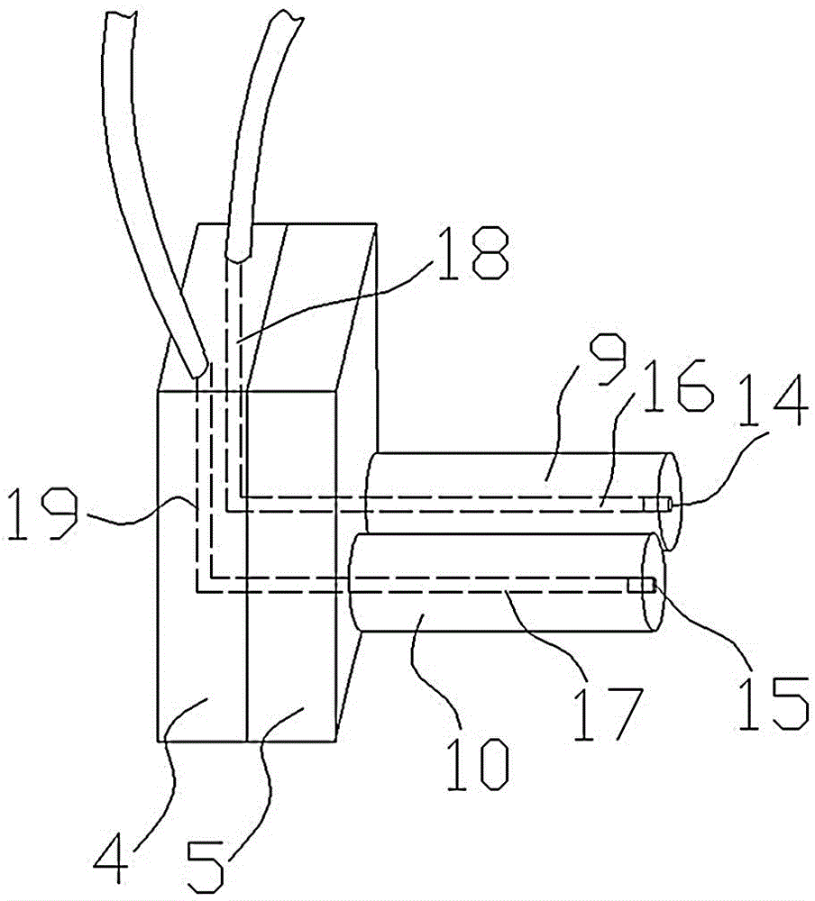
[0011] Such as figure 1 As shown, a kind of pneumatic demoulding injection mold for thermos bottle cap provided by the present invention comprises fixed mold 1 and movable mold, and movable mold comprises mold leg 2, top plate 3, thimble 6, water dividing plate 4, The core fixing plate 5, the push plate 8 and the first core 9 and the second core 10 which are arranged in parallel on the core fixing plate 5; One end of it is connected with the top plate 3, and the other end is formed to cooperate with the push plate 8; combined figure 2 As shown, the first core 9 and the second core 10 are respectively provided with a first air pipe 16 and a second air pipe 17 along the axial direction, and the end faces of the first core 9 and the second core 10 are respectively provided with a first air pipe. Mouth 14 and the second air nozzle 15, one end of the first air pipe 16 and the second air pipe 17 are respectively connected with the first air nozzle 14 and the second air nozzle 15, ...


PUM


Abstract

The invention discloses a pneumatic demolding injection molding mold for thermos bottle caps. The pneumatic demolding injection molding mold for thermos bottle caps sequentially comprises a fixed mold and a moving mold; the moving mold comprises a mold leg, an ejection plate, ejector pins, a water distribution plate, a mold core fixing plate, a pushing plate and mold cores; the mold cores are arranged on the mold core fixing plate; the pushing plate is matched with guide rods on the mold core fixing plate in a sliding mode. The pneumatic demolding injection molding mold for thermos bottle caps is characterized in that the mold cores are internally axially provided with air pipes; the end surfaces of the mold cores are provided with air nozzles; one ends of the air pipes are connected with the air nozzles, and the other ends of the air pipes are connected with an air source by air holes in the water distribution plate. Compressed air is sprayed into thermos bottle caps on the mold cores by the air pipes and the air nozzles, so that the thermos bottle caps are removed from the mold to achieve the aim of demolding automatically without manual operation; therefore, the production efficiency is improved.

Description

technical field [0001] The invention relates to the field of molds, in particular to a pneumatic demoulding injection mold for thermos bottle caps. Background technique [0002] As is known, the production and processing of thermos bottle caps generally heat the plastic through an injection molding machine, and then inject the molten plastic into the cavity of the injection mold after plasticization. The injection molding process can be roughly divided into the following six stages: "mold closing- Injection-holding-pressure-cooling-opening-product take-out"; the current thermos bottle cap injection mold generally includes a fixed mold and a moving mold, wherein the moving mold includes mold legs, top plate, thimble, water separating plate, core fixing plate, pusher Plate and core, after the mold is opened, the top plate in the movable mold drives the thimble to push the push plate to push out the thermos bottle cap on the core, but for the needs of injection mold closing, th...

Claims


Application Information

Patent Timeline
Patent Type & Authority Applications(China)
IPC IPC(8): B29C45/26B29C45/40B29C45/43
CPCB29C45/26B29C45/4005B29C45/43
Inventor 韩振刚
Owner 蚌埠市万达塑料制品有限公司
Why Eureka
Try Eureka