
A Three-Dimensional Spatial Stress-Strain Measurement Method Based on Fiber Bragg Grating Sensor

A fiber grating, stress-strain technology, applied in the field of optical fiber sensing, can solve problems such as no theory and method

Active Publication Date: 2016-09-28
成都毅莘瑞科技有限公司
View PDF5 Cites 0 Cited by
  • Summary
  • Abstract
  • Description
  • Claims
  • Application Information

AI Technical Summary

Problems solved by technology

There are no relevant theories and methods for stress and strain detection based on fiber grating sensors in three-dimensional space

Method used


Image

  • A Three-Dimensional Spatial Stress-Strain Measurement Method Based on Fiber Bragg Grating Sensor
  • A Three-Dimensional Spatial Stress-Strain Measurement Method Based on Fiber Bragg Grating Sensor
  • A Three-Dimensional Spatial Stress-Strain Measurement Method Based on Fiber Bragg Grating Sensor

Examples


Embodiment 1

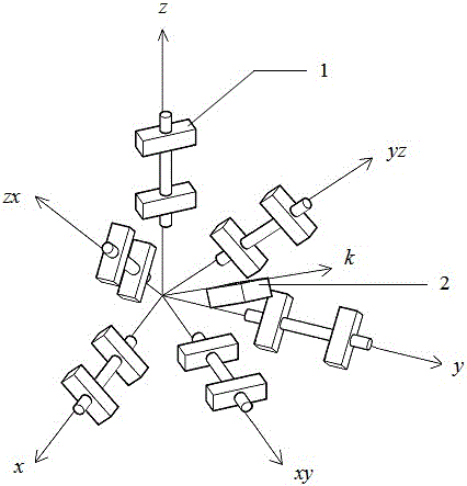
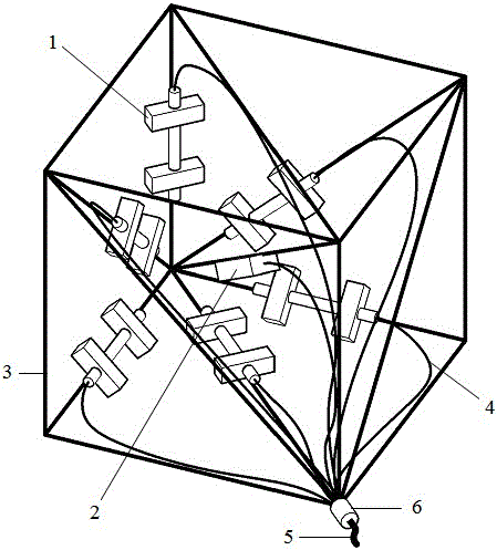
[0050] Such as figure 1 , figure 2 As shown, the present invention relates to a method for measuring stress and strain in three-dimensional space based on a fiber grating sensor, and the sensors used are all produced by Dalian University of Technology, including the following steps:

[0051] Step 1. Set 6 fiber grating strain sub-sensors (1) respectively on the xy, y, z three principal axes of the space coordinate system and the xoy plane, yoz plane, xy, yz on the position of the angle bisector in the zox plane, On the zx axis, that is, three adjacent edges of the three-dimensional metal frame 3 and the angle bisector between the two adjacent edges.

[0052] Step 2. Install the temperature sub-sensor 2 on the k-axis, that is, on the prism on the body diagonal of the three-dimensional metal frame 3 . Note that a certain distance should be kept between the sensors to prevent relative movement from being hindered during use. Lead the single optical fiber transmission line 4 o...


PUM


Abstract

The invention discloses a three-dimensional space stress-strain measurement method based on a fiber bragg grating sensor. The method comprises the following steps: arranging six fiber bragg grating strain sub-sensors on the three principal axes of a space coordinate system and the axes of angular bisectors between every two adjacent principal axes respectively; arranging a temperature sub-sensor on the axis k in the body diagonal direction of a cube; working out the strain in the directions of the six fiber bragg grating strain sub-sensors through a decoupling equation set of the fiber bragg grating sensor based on wavelength, wherein the wavelength is measured by the six fiber bragg grating strain sub-sensors and the temperature sub-sensor; obtaining the values of epsilon x, epsilon y, epsilon z, gama xy, gama yz and gama zx through the plane strain relationship formula of the mechanics of materials; substituting the six quantities into a cubic space principal strain equation to obtain the values of the principal strain epsilon 1, epsilon 2 and epsilon 3; obtaining the values of the principal stress sigma 1, sigma 2 and sigma 3 through a physical equation of the elastic mechanics; obtaining the directions of the principal strain and the principal stress through a space strain relationship equation set of the elastic mechanics and a direction cosine relational expression; obtaining the maximum value taw maximum of shear stress through the maximum shear stress formula; obtaining the direction of the maximum shear stress through the relationship between the principal stress and principal shear stress.

Description

technical field [0001] The invention relates to a method for measuring stress and strain, in particular to a method for measuring stress and strain in three-dimensional space based on an optical fiber grating sensor, and belongs to the technical field of optical fiber sensing. Background technique [0002] Due to the advantages of anti-electromagnetic interference, small size, light weight, and easy networking, fiber grating sensors have been widely used in concrete structure health monitoring. For example, Hong Kong Polytechnic T.H.T.Chan and others divided 40 fiber grating sensors into three groups and arranged them in the suspension cables, rocker bearings and truss beams of the Tsing Ma Bridge in Hong Kong, and measured the strains of different parts under different loads of railways and highways. . The Swiss Federal Materials Testing and Research Laboratory installed fiber grating sensors in the Luzzone Dam to monitor the safety of the dam. [0003] However, the stres...

Claims


Application Information

Patent Timeline
Patent Type & Authority Patents(China)
IPC IPC(8): G01L1/24G01B11/16
Inventor 孙丽张博朱万成
Owner 成都毅莘瑞科技有限公司
Learn More