Eureka AIR delivers breakthrough ideas for toughest innovation challenges, trusted by R&D personnel around the world.
A plug-in led deck
What is Al technical title?
Al technical title is built by PatSnap Al team. It summarizes the technical point description of the patent document.
A card holder and socket technology, which is applied in the field of electric light source sockets, can solve problems such as poor contact of socket wires and electric light source separation from sockets, etc., and achieves high social application value and economic added value. The structure is beautiful and the structure is exquisite.
Active Publication Date: 2016-01-27
安徽省皖凯机械有限公司
View PDF4 Cites 0 Cited by
Summary
Abstract
Description
Claims
Application Information
AI Technical Summary
This helps you quickly interpret patents by identifying the three key elements:
Problems solved by technology
Method used
Benefits of technology
Problems solved by technology
[0003] The purpose of the present invention is to overcome the defects of the current known electric light source sockets such as poor contact of the socket wires during high-speed movement, and the electric light source is out of the socket, and to provide the public with a unique plug-in LED electric light source socket device
Method used
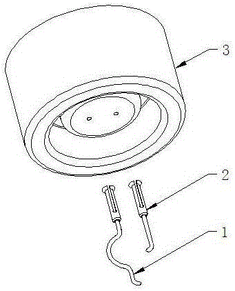
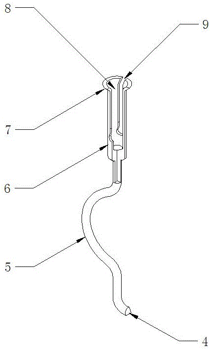
Image
Click on the blue label to locate the original text in one second.
Reading with bidirectional positioning of images and text.
Examples
Embodiment Construction
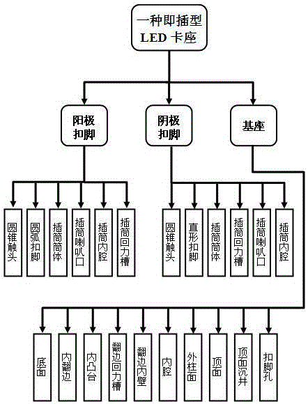
[0028] The present invention, as a technical solution for product manufacturing, can be implemented through the organic combination of corresponding organizational structures. The product organization structure of an embodiment of the present invention is as follows: figure 1 shown.
[0029] figure 1 Among them, the product is composed of three parts: the anode buckle, the cathode buckle, and the base. There are six components of the pull-back groove of the cylinder. The structure of the cathode buckle part includes six components: the conical contact, the straight buckle, the socket, the pull-back groove of the socket, the bell mouth of the socket, and the inner cavity of the socket. The structure of the base part includes Bottom surface, inner flange, inner boss, flange return groove, flange inner wall, inner cavity, outer cylinder, top surface, top caisson, and buckle foot hole are ten components.
[0030] In the embodiment, the specific form of each part of the product ...
PUM
Abstract
The invention relates to an electric light source socket, in particular to a plug-and-play ultramicro clamp base which is suitable for high-speed movement of an LED electric light source matrix. The clamp base is composed of three parts of a substrate, a positive electrode buckle and a negative electrode buckle and structurally comprises 22 parts of a conical contactor, an arc buckle, an insert barrel, an insert barrel horn opening, an insert barrel inner cavity, an insert barrel rebounding groove, a straight buckle, an inner turnup, an inner boss, a turnup rebounding groove, a turnup inner wall, an inner cavity, an outer cylinder face, a top face, a top face open caission, a buckle hole and the like. The plug type LED clamp base has the advantages of being ingenious in structure, reliable in operation, wide in application and the like and overcoming the defects that an existing general electric light source socket is poor in wire contact in high-speed movement, the electric light source is prone to break away and the like. In addition, the plug type LED clamp base also has the advantages of being simple to implement, easy to manufacture, attractive in appearance, solid and durable in structure, convenient to use, wide in market space and higher in economical added value.
Description
technical field [0001] The invention relates to an electric light source socket, in particular to a plug-and-play supermicro card socket which can be used for high-speed movement of LED electric light source arrays. Background technique [0002] Electric light source socket refers to a physical device used to connect electric light sources such as incandescent lamps, fluorescent lamps, and arc lamps to current wires and fix them. Currently known electric light source sockets generally have two types of electric light source fixing methods, plug-in type and rotary type, namely so-called screw sockets and bayonet sockets. In the case of sports, especially in high-speed rotary motion, these known electric light source sockets (whether screw sockets or bayonet sockets) are likely to cause defects such as poor contact of socket wires and electric light sources falling out of sockets, thereby affecting the known electric light source sockets. The use function, application range a...
Claims
Application Information
Patent Timeline
Application Date:The date an application was filed.
Publication Date:The date a patent or application was officially published.
First Publication Date:The earliest publication date of a patent with the same application number.
Issue Date:Publication date of the patent grant document.
PCT Entry Date:The Entry date of PCT National Phase.
Estimated Expiry Date:The statutory expiry date of a patent right according to the Patent Law, and it is the longest term of protection that the patent right can achieve without the termination of the patent right due to other reasons(Term extension factor has been taken into account ).
Invalid Date:Actual expiry date is based on effective date or publication date of legal transaction data of invalid patent.