
Welding fixture with turnover bottom plate

A welding jig and bottom plate technology, which is applied to the field of welding fixtures with reversible bottom plates, can solve the problems of large number of production personnel, complicated operation process, affecting production rhythm, etc., to reduce the number of fixtures, ensure uninterrupted production, and high production efficiency Effect

Inactive Publication Date: 2014-08-06
SHANGHAI ANDELAI AUTO PARTS
View PDF0 Cites 0 Cited by
  • Summary
  • Abstract
  • Description
  • Claims
  • Application Information

AI Technical Summary

Problems solved by technology

This kind of welding fixture is usually limited by the design, resulting in too much time-consuming in the process of picking and placing parts, which seriously affects the production cycle, and the operation process is complicated, requiring a large number of fixtures and production personnel, which increases a lot of production costs.

Method used


Image

  • Welding fixture with turnover bottom plate
  • Welding fixture with turnover bottom plate
  • Welding fixture with turnover bottom plate

Examples


Embodiment

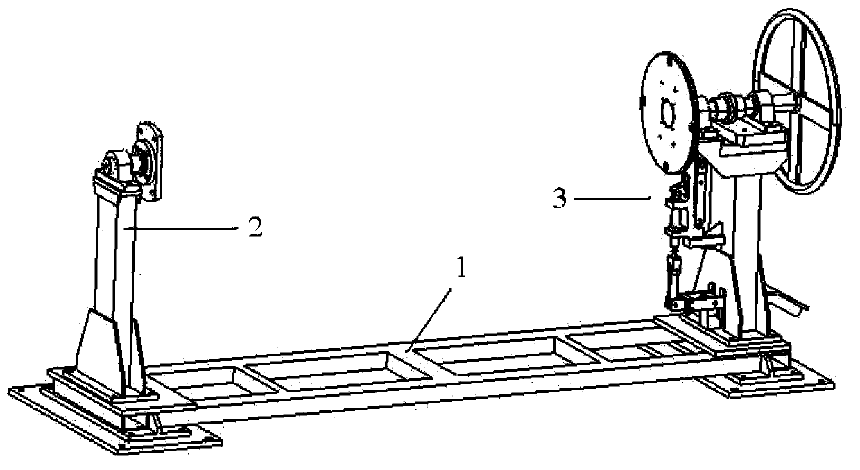
[0021] A welding jig with a reversible bottom plate, its structure is as follows figure 1 As shown, it is composed of a fixture main body 1 and a front welding turning table 2 and a rear welding turning table 3 connected to both ends of the fixture body. The front welding turning table 2 and the rear welding turning table 3 are connected with a welded part and drive the part to rotate.

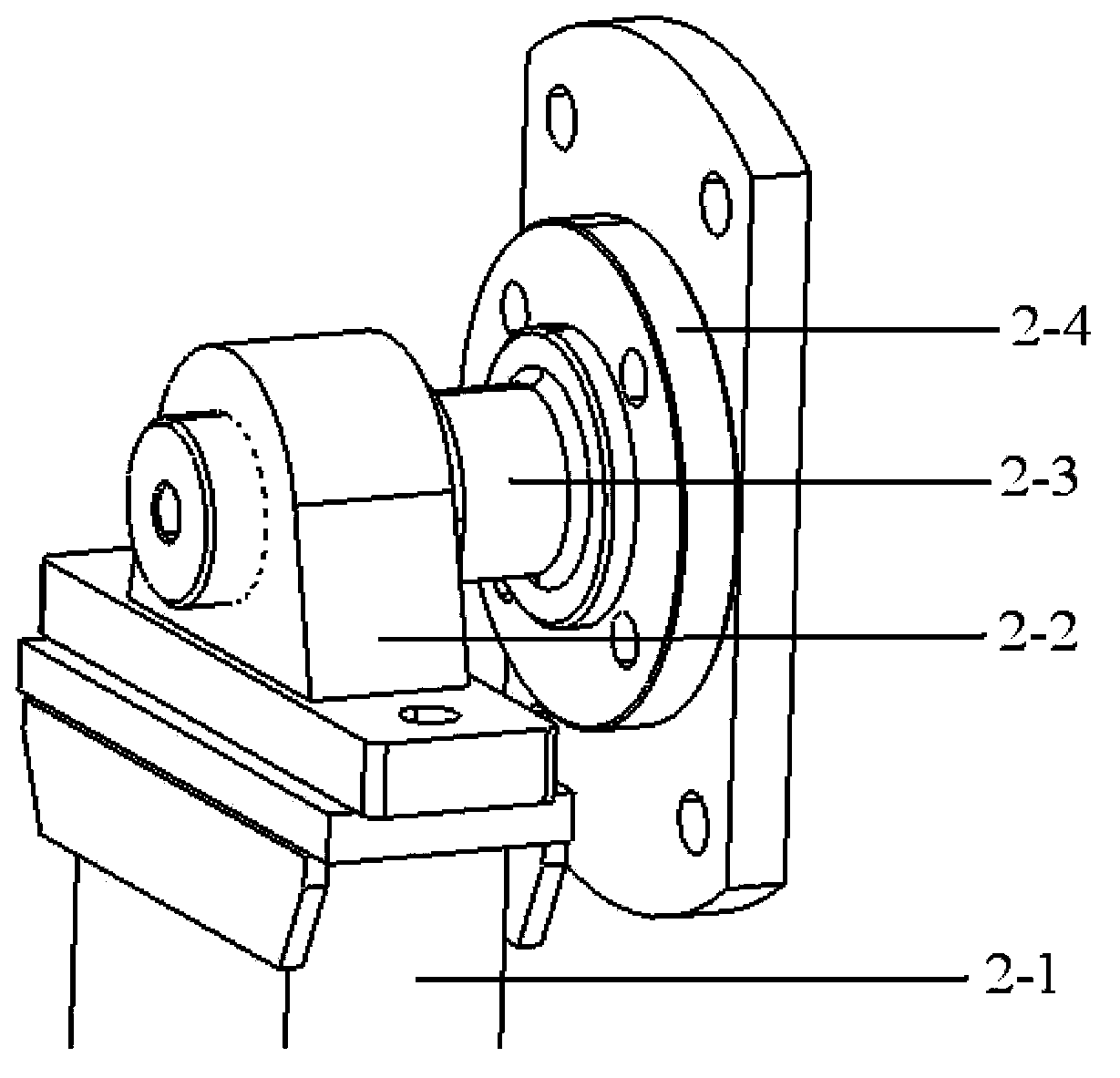
[0022] The structure of the front welding turning table 2 is as follows figure 2 As shown, including welding bracket 2-1, bearing seat 2-2, self-aligning bearing 2-3 and reinforcement device 2-4, welding bracket 2-1 is supported and connected to the front end of fixture main body 1, and self-aligning bearing 2-3 is The bearing seat 2-2 is connected to the top of the welding bracket 2-1, and the reinforcing device 2-4 is connected with the self-aligning bearing 2-3, and the reinforcing device 2-4 is used for fixedly connecting parts to be welded.

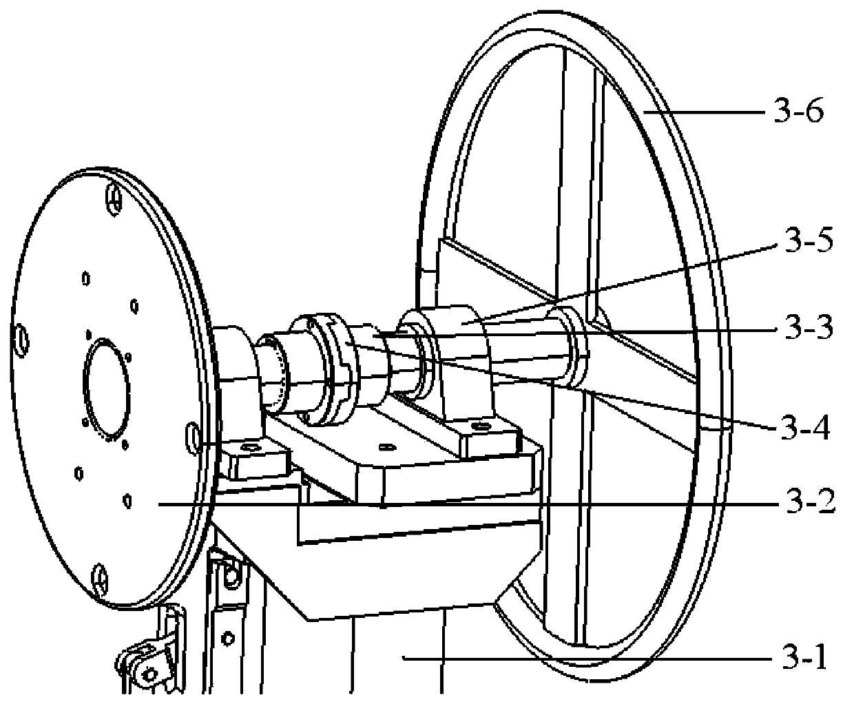
[0023] The structure of the rear welding tur...


PUM


Abstract

The invention relates to a welding fixture with turnover bottom plate. The welding fixture consists of a fixture main body, a front welding turnover table and a rear welding turnover table, wherein the front welding turnover table and the rear welding turnover table are connected to two ends of the fixture main body; and the front welding turnover table and the rear welding turnover table are connected with a welding part and drive the part to rotate. Compared with the prior art, the welding fixture with the turnover bottom plate has the advantages that the welding part can be driven to rotate, the other surface of the part is not required to be welded after the part is taken down, the welding fixture is high in production efficiency and convenient to repair, and is safe and reliable, and the cost is saved.

Description

technical field [0001] The invention relates to a welding jig, in particular to a welding jig with a reversible bottom plate. Background technique [0002] At present, the welding of parts is usually carried out on welding fixtures. Usually, the part is placed on the welding fixture, positioned through the positioning hole, and then the surface of the part is pressed by a pressing mechanism to fix it, and then welded. However, in the actual welding process, some parts need to be welded on two or more sides, especially the base plate parts are relatively large. In this case, the parts need to be removed after one side is welded, and then placed on another fixture for welding. This kind of welding fixture is usually limited by the design, resulting in too much time-consuming in the process of picking and placing parts, which seriously affects the production cycle, and the operation process is complicated, requiring a large number of fixtures and production personnel, which in...

Claims


Application Information

Patent Timeline
Patent Type & Authority Applications(China)
IPC IPC(8): B23K37/047
CPCB23K37/047B23K37/0443
Inventor 赵庆博左世伟顾成治
Owner SHANGHAI ANDELAI AUTO PARTS
Learn More