Electric double support and its electric car or motorcycle

A technology of electric vehicles and double legs, applied in bicycle accessories, bicycle brackets, transportation and packaging, etc., can solve the problems of time-consuming and laborious, unable to lift the rear end of the vehicle, etc., and achieve the effect of convenient use and fast speed.

Inactive Publication Date: 2016-04-27
常州市爱多动力科技有限公司
View PDF5 Cites 0 Cited by
  • Summary
  • Abstract
  • Description
  • Claims
  • Application Information

AI Technical Summary

Problems solved by technology

[0003] The disadvantage of the above-mentioned traditional double supports is that it is time-consuming and labor-intensive to use, especially for heavy-duty electric vehicles or motorcycles, and generally a single user cannot lift the rear end of the vehicle

Method used


Image

  • Electric double support and its electric car or motorcycle
  • Electric double support and its electric car or motorcycle
  • Electric double support and its electric car or motorcycle

Examples


Embodiment 1

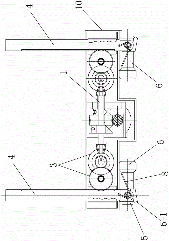
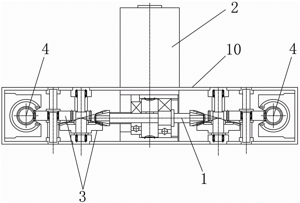
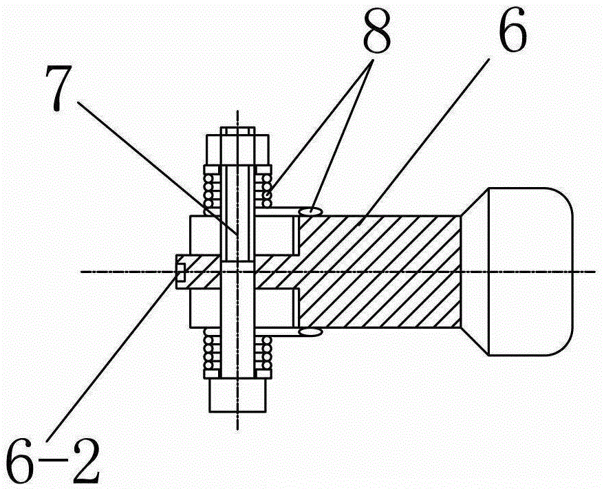
[0023] See Figure 1-3 , the electric double support feet of this embodiment include: a pair of support rods 4 that are driven and matched with the support foot motor 2 and are suitable for up and down synchronous displacement; ; The outer side surface of the top end of each foot rod 6 is provided with an extension extending outward, and the top end of the extension portion constitutes a meshing tooth 6-1, or the top end of the extension portion is provided with a pulley; There is an engagement seat 5; when each strut 4 is displaced upward, the engagement seat 5 and the engagement teeth 6-1 are suitable for meshing with each other, or the engagement seat 5 and the pulley are slidably matched, and are suitable for the pair of struts 4 Swing inward until it is in a horizontal state; when each support rod 4 is displaced downward, the meshing seat 5 and the meshing teeth 6-1 are separated from each other, and the pair of foot rods 6 are suitable for lowering and maintaining a larg...

Embodiment 2

[0034] An electric vehicle using the above electric double-leg support includes: a power key switch, the power key switch including: a neutral gear suitable for cutting off the power of the support motor and the main motor of the electric vehicle, and suitable for turning on only the electric vehicle owner The driving gear of the motor power supply is suitable for only turning on the parking gear of the support foot motor power supply.

[0035]The electric vehicle further comprises: a sensor for detecting whether the wheel on which the main motor of the electric vehicle is located is rotating, the sensor is connected with the controller of the electric vehicle; when the controller detects that the wheel is stopped by the sensor, and When the power key switch is in the parking gear position, the power of the foot motor is turned on. The sensor is a Hall sensor in the main motor of the electric vehicle; or the sensor includes: a plurality of permanent magnets evenly distributed ...


PUM


Abstract

The invention relates to electrically-driven double arm-braces. The electrically-driven double arm-braces comprise a pair of supporting rods matched with an arm-brace motor in a transmission manner, and a pair of footing rods hinged with the bottom ends of the supporting rods respectively, wherein an extending part extendingoutwardly is arranged on the outer side surface of the top end of each footing rod; a meshing tooth is formed at the top end of each extending part, or a pulley is arranged at the top end of eachextending part; a meshing seat is fixedly arranged at the upper part of a position adjacent to each extending part; when each supporting rod is in upward displacement, the meshing seat is meshed with the meshing tooth, or is in sliding fit with the pulley, and is suitable for allowing the supporting rods to swing towardsthe inner side until to be in the horizontal state; when each supporting rodis in downward displacement, the meshing seat and the meshing tooth are separatedfrom each other, and the footing rods are suitable for swinging downwards and present in a splay shape. When the electrically-driven double arm-braces are in use, supporting rods continue downward synchronous displacement until being in contact with the ground and supporting up the rear end part of an electric motorcar or a motorcycle so as to fix the electric motorcar or the motorcycle, and moreover, labor is not required.

Description

technical field [0001] The invention relates to a supporting device for an electric vehicle or a motorcycle, in particular to an electric double supporting foot. Background technique [0002] The supporting device for electric vehicles or motorcycles in the prior art is generally a diagonal brace or double braces with tension springs. Use your feet to push the double feet into the hem position. [0003] The disadvantage of the above-mentioned traditional double support feet is that it is time-consuming and labor-intensive to use, especially for heavy electric vehicles or motorcycles, and generally a single user cannot lift the rear end of the vehicle. SUMMARY OF THE INVENTION [0004] The technical problem to be solved by the present invention is to provide an electric double support foot which is simple in structure, easy to use and effortless. [0005] In order to solve the above-mentioned technical problems, the present invention provides an electric double support fo...

Claims


Application Information

Patent Timeline
Patent Type & Authority Patents(China)
IPC IPC(8): B62H1/04
Inventor 刘云鹤蔡华勇孙云鹏孙道清
Owner 常州市爱多动力科技有限公司
Why Eureka
Try Eureka