A conveyor chain for the cooling frame of the normalizing furnace

A technology for conveying chains and cooling racks, which is applied in the field of normalizing furnace equipment production, which can solve the problems of inability to convey, insignificant cooling effect, poor thermal conductivity of carbon steel wires, etc., and achieve good air permeability

Active Publication Date: 2016-05-18
YIXING JIUMING TECH
View PDF3 Cites 0 Cited by
  • Summary
  • Abstract
  • Description
  • Claims
  • Application Information

AI Technical Summary

Problems solved by technology

[0002] The conveying chain of this normalizing cooling rack is the key construction of isothermal normalizing heat treatment process. The traditional mesh belt structure has defects such as poor air permeability and short service life. The main reason is that the traditional mesh belt is mostly a mesh structure woven by steel wire. Its material is mostly carbon steel with strong toughness, otherwise it is difficult to meet the requirements of bending and weaving, and it is easy to break, while the thermal conductivity of carbon steel wire is poor, and it is easy to deform during repeated temperature changes, and the mesh belt woven by it The mesh is small, and the heat cannot be volatilized in time, resulting in inconspicuous cooling effect, which reduces the efficiency of the normalizing furnace, thus failing to meet the requirements of the normalizing process. Moreover, most of the mesh belts in the prior art are equipped with drive rollers before and after the product is used. The mesh belt is directly wound on the transmission roller, and the transmission is carried out by the tension force between the mesh belt and the roller surface. Its main defect is that the mesh belt is easily deformed after being affected by temperature, resulting in insufficient tension, resulting in failure to convey. Room for improvement

Method used


Image

  • A conveyor chain for the cooling frame of the normalizing furnace
  • A conveyor chain for the cooling frame of the normalizing furnace
  • A conveyor chain for the cooling frame of the normalizing furnace

Examples


Embodiment Construction

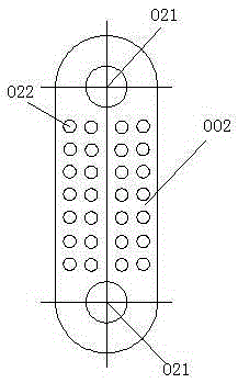
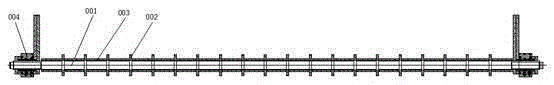
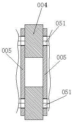
[0015] A conveying chain for a cooling frame of a normalizing furnace, the conveying chain is horizontally arranged in the furnace body, one end protrudes from the feed port, and the other end protrudes from the discharge port, and the conveying chain includes a plurality of piercing shafts 001 arranged in parallel, and piercing shafts The chain plate 002 hinged by the mandrel 001, the spacer 003 sleeved on the mandrel 001, and the sleeves 004 coaxial with the mandrel 001 at both ends of the mandrel 001, the chain plate 002 is a round rectangular plate Body, with symmetrical through holes 021 at both ends, one end through hole 021 is set on a through mandrel 001, the other end through hole 021 is set on the adjacent through mandrel 001, and the spacer 003 is used between adjacent chain plates 002 Separated from each other, the upper chain plates 002 of the adjacent through-core shafts 001 are arranged in a staggered manner. The chain plate 002 is martensitic stainless steel. ...


PUM

PropertyMeasurementUnit
lengthaaaaaaaaaa

Abstract

A normalizing furnace cooling bracket conveying chain adopts the scheme that a conveying chain is horizontally arranged inside a furnace body; one end of the conveying chain extends out of a feeding opening, and the other end of the conveying chain extends out of a discharging opening; the conveying chain comprises a plurality of center-penetrating shafts arranged in parallel, chain plates hinged to the center-penetrating shafts, separation sleeves arranged on the center-penetrating shafts in a sleeving manner, and shaft sleeves arranged at the two ends of the center-penetrating shafts and movably connected with the center-penetrating shafts; the chain plates are round rectangular plate; symmetric through holes are formed in the two ends of each chain plate; one through hole in one end of one chain plate sleeves one center-penetrating shaft, and the other through hole in the other end of the chain plate sleeves an adjacent center-penetrating shaft; every two adjacent chain plates are separated from each other by each separation sleeve; the chain plates on every two adjacent center-penetrating shafts are arranged in a staggered manner. The normalizing furnace cooling bracket conveying chain is high in conveying efficiency, excellent in heat dissipation performance, and long in service life.

Description

technical field [0001] The invention relates to the field of normalizing furnace equipment manufacturing, in particular to a conveying chain for forced cooling of the normalizing furnace. Background technique [0002] The conveying chain of this normalizing cooling rack is the key construction of isothermal normalizing heat treatment process. The traditional mesh belt structure has defects such as poor air permeability and short service life. The main reason is that the traditional mesh belt is mostly a mesh structure woven by steel wire. Its material is mostly carbon steel with strong toughness, otherwise it is difficult to meet the requirements of bending and weaving, and it is easy to break, while the thermal conductivity of carbon steel wire is poor, and it is easy to deform during repeated temperature changes, and the mesh belt woven by it The mesh is small, and the heat cannot be volatilized in time, resulting in inconspicuous cooling effect, which reduces the efficien...

Claims


Application Information

Patent Timeline
Patent Type & Authority Patents(China)
IPC IPC(8): C21D1/28
Inventor 李仁振詹磊
Owner YIXING JIUMING TECH
Why Eureka
Try Eureka