
A Visual Ultrasonic Detection Method for Partial Discharge Fault Detection

A partial discharge and fault detection technology, applied in radio wave measurement systems, measurement devices, testing dielectric strength and other directions, can solve problems such as manual search for the location of sound sources, errors in positioning results, and detection results that are not presented to users in a visual way. Achieve the effect of realizing ultrasonic positioning, high-precision ultrasonic positioning, and visual detection and positioning

Active Publication Date: 2017-01-25
SHANGHAI ENERGYFUTURE +4
View PDF5 Cites 0 Cited by
  • Summary
  • Abstract
  • Description
  • Claims
  • Application Information

AI Technical Summary

Problems solved by technology

At present, many research institutions at home and abroad have carried out research on partial discharge detection based on ultrasound. However, most of the existing research is oriented to the automatic positioning of partial discharge, but the positioning results often have errors due to various interferences and obstacles. The results are not presented to the user in a visual way, and many of them are ultrasonic detection equipment based on a single sensor, which requires manual search for the location of the sound source

Method used


Image

  • A Visual Ultrasonic Detection Method for Partial Discharge Fault Detection
  • A Visual Ultrasonic Detection Method for Partial Discharge Fault Detection
  • A Visual Ultrasonic Detection Method for Partial Discharge Fault Detection

Examples


Embodiment Construction

[0025] The present invention will be further described below in conjunction with the accompanying drawings and embodiments.

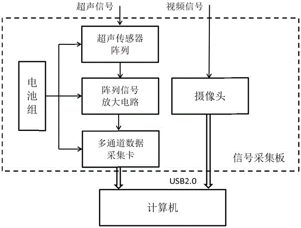
[0026] as attached figure 1 As shown, this embodiment involves three main parts: signal acquisition, signal processing, and result visualization, namely: firstly, the ultrasonic sensor array is used to collect the ultrasonic signals that appear in the power equipment, and the spatial distribution of ultrasonic intensity is estimated; at the same time The video signal of the scene is collected, and then based on the acquired ultrasonic signal and video signal, the spatial distribution of ultrasonic intensity is visualized, so as to intuitively display the spatial position of the partial discharge point as the ultrasonic source.

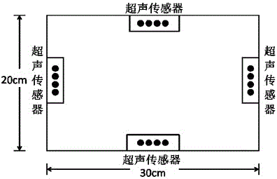
[0027] as attached figure 2 As shown, the collection of the above-mentioned ultrasonic signal and video signal in the present embodiment adopts an ultrasonic and video centralized acquisition board to collect; the ultrasonic a...


PUM


Abstract

The invention relates to a visual ultrasonic detection method for partial discharge failure detection. The method is characterized in that an ultrasonic sensor array is firstly adopted to acquire ultrasonic signals generated by power equipment, and ultrasonic intensity space distribution is evaluated; and meanwhile, video signals are acquired on the scene, and the ultrasonic intensity space distribution is visualized on the basis of the acquired ultrasonic signals and video signals, thereby visually displaying the space position of the partial discharge point as an ultrasonic source. By researching the partial discharge failure detection of the power equipment and designing the visual ultrasonic detection according to the distribution characteristics of the generated ultrasonic signals in the time domain and frequency domain, the system can detect the partial discharge phenomenon in the power equipment at high precision.

Description

technical field [0001] The invention relates to the field of fault detection of electric equipment, in particular to a visual ultrasonic detection method for partial discharge fault detection. Background technique [0002] Partial discharge is a fault phenomenon that needs to be detected in time in power equipment. It will cause insulation degradation of equipment and accelerate the process of insulation damage. Avoiding and removing partial discharge in time, so that the normal and safe operation of equipment has become the most important thing for power equipment maintenance personnel. In order to eliminate this latent fault phenomenon, many methods for online detection of partial discharge phenomenon have appeared. [0003] The detection of partial discharge is based on various physical phenomena generated by it, and the state, characteristics and location of the discharge are estimated. During the partial discharge process, electric pulses, electromagnetic radiation, ul...

Claims


Application Information

Patent Timeline
Patent Type & Authority Patents(China)
IPC IPC(8): G01R31/12G01S5/20
Inventor 赵文彬张志平葛耿民聂俊胜
Owner SHANGHAI ENERGYFUTURE
Learn More