Water stop structure for water inlet device of toilet bowl

A technology for water inlet devices and water tanks, applied in water supply devices, flushing equipment with water tanks, buildings, etc., can solve the problems of increased lateral dimensions, increased unstable factors, time-consuming and troublesome problems, and achieves reduced wear and tear, convenient installation and Debugging and ensuring the effect of pressure stability

Active Publication Date: 2014-08-13
广东恒通达科技有限公司
View PDF5 Cites 3 Cited by
  • Summary
  • Abstract
  • Description
  • Claims
  • Application Information

AI Technical Summary

Problems solved by technology

For this reason, in the prior art, it is often used to increase the area of ​​the buoyancy bucket to increase the buoyancy to improve the sealing performance of the water, or to increase the lever ratio of the lifting bar in order to increase the force so as to achieve high pressure resistance. This adjustment brings the most direct effect The impact is that the volume of the water inlet device will increase, especially the lateral dimension in the water tank, and at the same time, the local structure of the product will be stressed, which will increase the instability of the product
[0003] On the other hand, the existing design of the lever structure on the top of the water inlet device also limits that the structure can only be designed as a fixed structure, and it is difficult to realize the adjustable requirements. If it is correct, you have to loosen the lock nut again, adjust the direction and lock it again, which is time-consuming and troublesome, and repeated disassembly and assembly of the product is not good for the product itself (mainly composed of plastic parts)

Method used


Image

  • Water stop structure for water inlet device of toilet bowl
  • Water stop structure for water inlet device of toilet bowl
  • Water stop structure for water inlet device of toilet bowl

Examples


Embodiment Construction

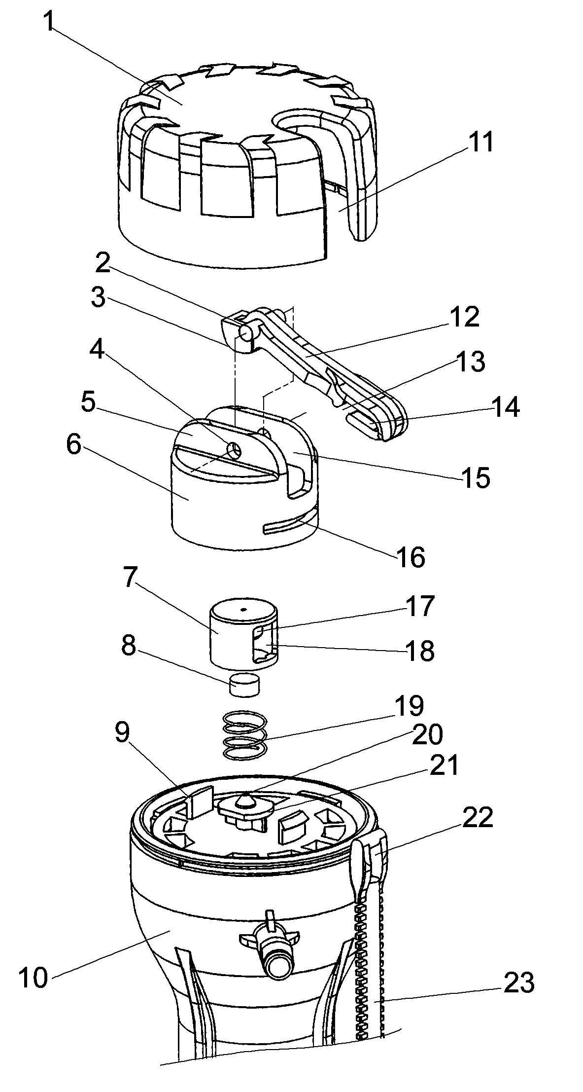
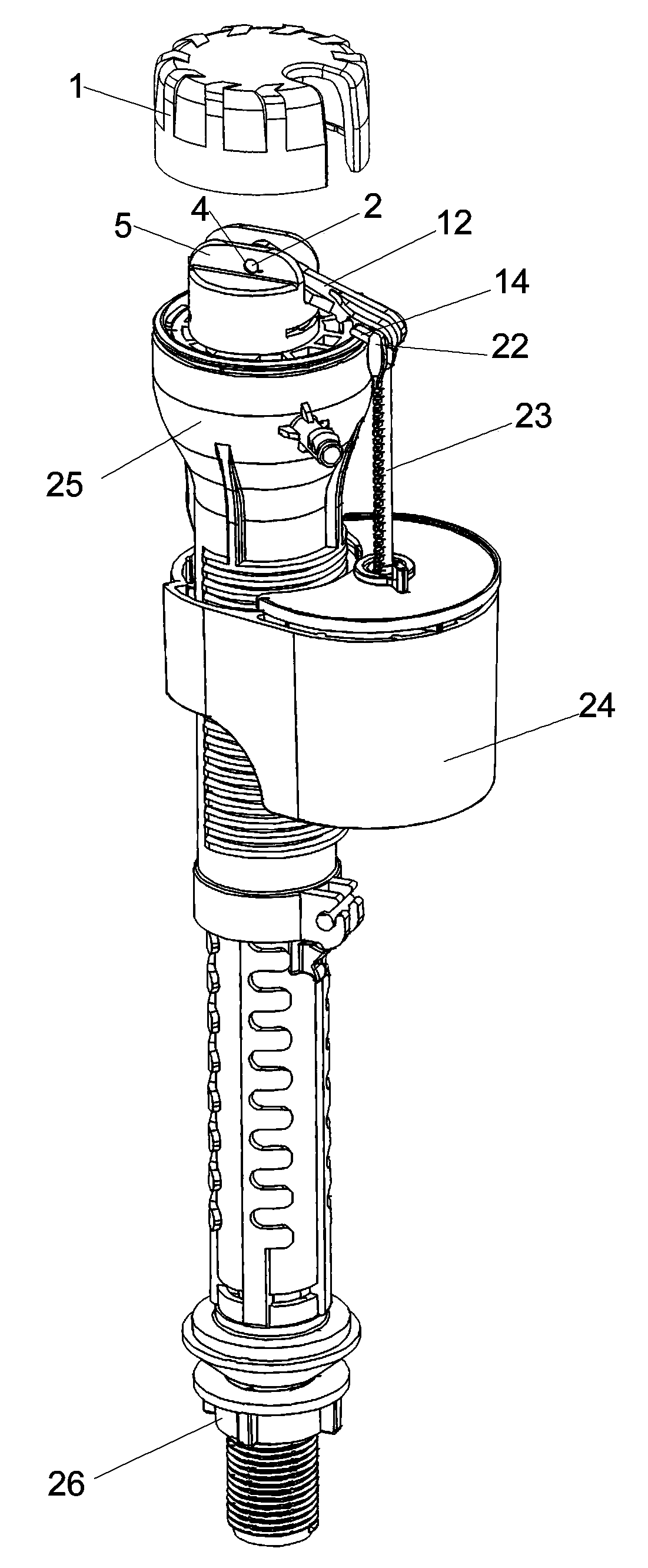
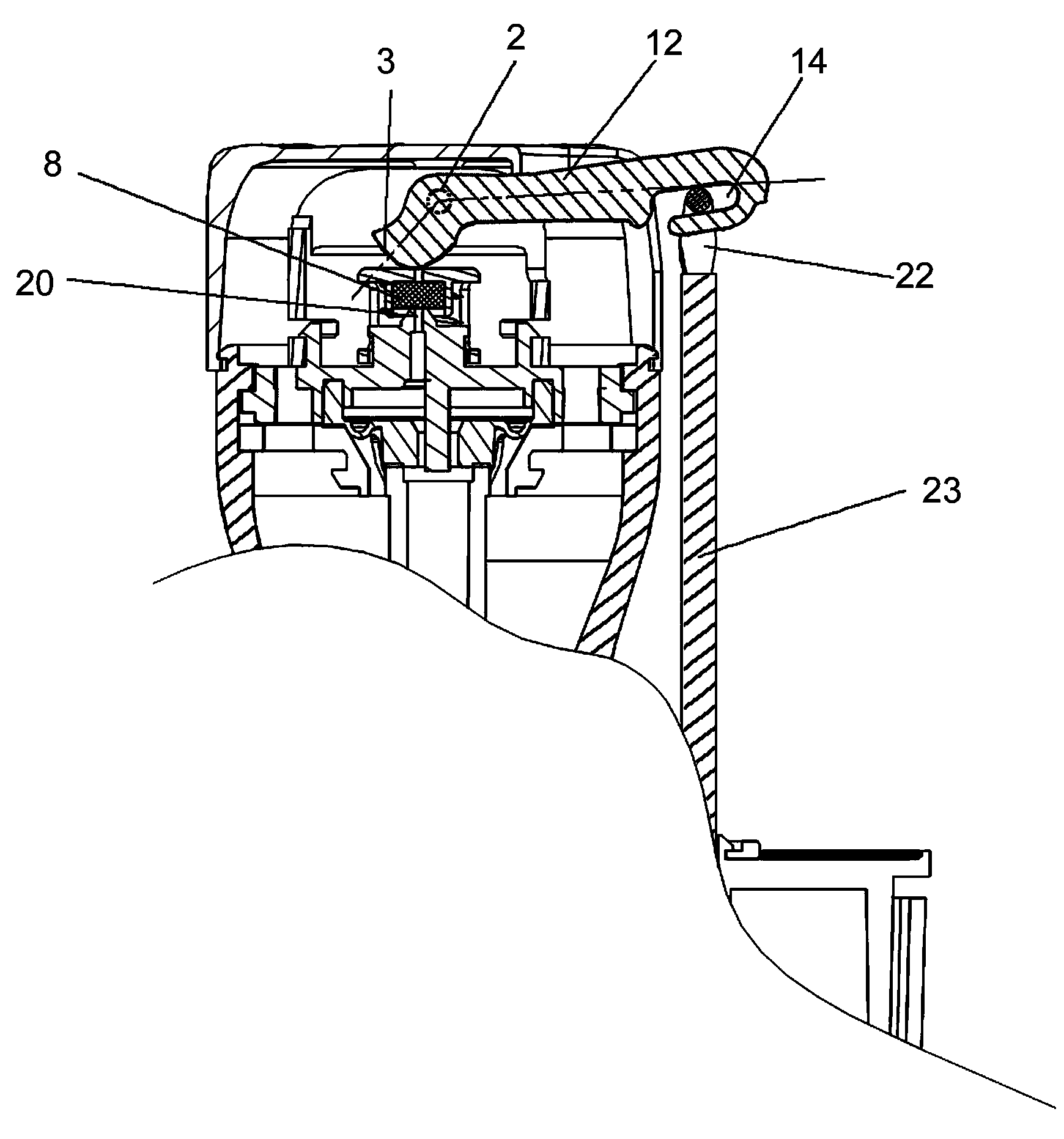
[0021] As shown in the figure, the present invention is a water stop structure suitable for the water inlet device of the toilet tank, including a water inlet valve 10, the bottom of which can be fixed in the toilet water tank through a nut 25, and a ventilator is provided at the center of the top surface of the water inlet valve 10. Seat platform, air vent 20 is provided on the table top of ventilation seat, and convex edge 21 is provided on both sides of ventilation seat platform. Press the round cover 7, the top of the press round cover 7 is provided with a circular groove 17, a sealing gasket 8 is filled in the circular groove 17, a spring 19 is connected outside the circular groove 7, and the two sides of the pressed circular cover 7 are hollowed out as guides. Window 18, press the round cover 7 through the lower window frame and the convex edge 21 of the ventilation seat platform, and the lower window frame is limited to move in the limit structure formed between the conv...


PUM


Abstract

The invention relates to a water stop structure for a water inlet device of a toilet bowl. The structure comprises a water inlet valve and a lever support, wherein a ventilation seat stand is arranged at the center of the top surface of the water inlet valve, and a ventilation hole is formed in the surface of the ventilation seat stand. The structure is characterized in that convex edges are arranged on the two sides of the ventilation seat stand, the convex edges are connected with a pressing round cover in a clamped mode, a round groove is formed in the top of the interior of the pressing round cover, the round groove is filled with a sealing gasket, and a spring is connected to the outer side of the round groove in a sleeved mode; the lever support is clamped on the pressing round cover, a shaft hole is formed in the lever support, a lever swing arm is movably connected to the lever support through a rotary shaft and the shaft hole, a cam surface is arranged on one side of the lever swing arm and is in contact with the top surface of the pressing round cover in an abutting mode, and a slide-guiding groove is formed in the other side of the lever swing arm and is connected with a lifting rod connected to a float. The structure has the advantages of being small in structural member size, capable of achieving linkage transmission, high in lever ratio, suitable for high-pressure water supply and convenient to install and use.

Description

technical field [0001] The invention belongs to the field of valve accessories matched with water tanks, and in particular relates to a water stop structure suitable for a water inlet device of a toilet water tank. Background technique [0002] The water inlet devices currently on the market that are suitable for toilet tanks, whether through a piston-type water-stop structure or a back-pressure type water-stop structure, all have differences between the water supply pressure of the pipeline and the size of the floating bucket and the lever ratio of the lifting rod. Contradictory issues, the product must be able to withstand greater pipeline water supply pressure, especially in the current high-rise building water supply or some specific areas, it is required that the product can withstand higher water supply pressure. For this reason, in the prior art, it is often used to increase the area of ​​the buoyancy bucket to increase the buoyancy to improve the sealing performance ...

Claims


Application Information

Patent Timeline
Patent Type & Authority Applications(China)
IPC IPC(8): E03D1/32
Inventor 陈福山陈丰
Owner 广东恒通达科技有限公司
Why Eureka
Try Eureka