Permafrost region road tunnel peripheral hole blasting construction method

A technology for road tunnels and construction methods, which is applied in blasting and other directions, can solve problems such as permafrost thermal thawing and landslides, and achieve the effects of reducing blasting temperature, cost, and blasting heat

Inactive Publication Date: 2014-08-13
TONGJI UNIV
View PDF4 Cites 20 Cited by
  • Summary
  • Abstract
  • Description
  • Claims
  • Application Information

AI Technical Summary

Problems solved by technology

[0003] In order to solve the problem of permafrost hot-thaw landslides caused by blasting construction of highway tunnels in permafrost regions, this invention proposes a multi-year Blasting Excavation Method for Peripheral Hole of Highway Tunnel in Permafrost Region

Method used


Image

  • Permafrost region road tunnel peripheral hole blasting construction method
  • Permafrost region road tunnel peripheral hole blasting construction method
  • Permafrost region road tunnel peripheral hole blasting construction method

Examples


Embodiment 1

[0029] Embodiment one ( full face excavation )

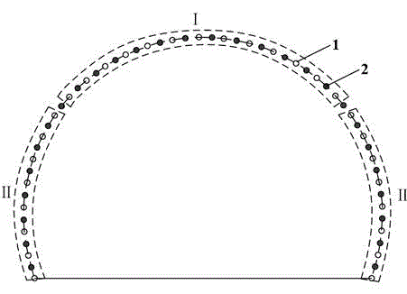
[0030] Step 1: Determine the excavation method and the depth of single-cycle footage according to the grade of the surrounding rock of the tunnel: for the surrounding rock of grade IV and above, the full-section method is adopted for excavation; the charge volume of the surrounding holes is designed to be 3 volumes; the footage is drilled in each blasting cycle The depth is not greater than 1.5m, and the distance between adjacent blastholes is not greater than 60cm. Such as figure 1 shown.

[0031] Step 2: Drill peripheral holes according to the specified spacing according to the excavation outline position of the tunnel design.

[0032] Step 3: After drilling into the hole, use a high-pressure air gun to clean the hole.

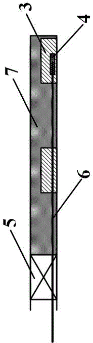
[0033] Step 4: Carry out the explosive loading of each blasthole 1 and the connection of the detonator 4 and the detonating cord 6 . Such as image 3 shown , the non-millisecond detonator 4 and the ...

Embodiment 2

[0036] Embodiment two ( step excavation )

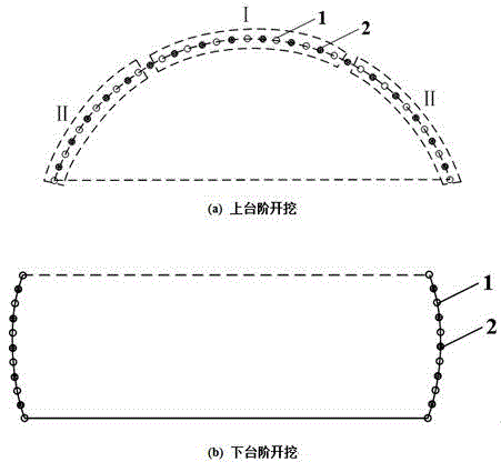
[0037] Step 1: Determine the excavation method and single-cycle footage depth according to the grade of the surrounding rock of the tunnel: for grade VI and grade V surrounding rock, the step method is adopted for excavation; the charge volume of the surrounding holes is designed to be 2 rolls; each blasting cycle The footage depth is not more than 1m, and the distance between adjacent blastholes is 50cm. Such as figure 2 shown.

[0038] Step 2: Drill peripheral holes according to the specified spacing according to the excavation outline position of the tunnel design.

[0039] Step 3: After drilling into the hole, use a high-pressure air gun to clean the hole.

[0040] Step 4: Carry out the explosive loading of each blasthole 1 and the connection of the detonator 4 and the detonating cord 6 . Such as image 3 shown , the non-millisecond detonator 4 and the non-electric detonating cord 6 are used to connect the detonation n...


PUM


Abstract

The invention relates to the field of tunnel construction, in particular to a permafrost region road tunnel peripheral hole blasting construction method. The method comprises the following steps of step 1, according to the grade of a tunnel peripheral rock, determining a digging way and the single-circulation advanced depth; step 2, according to the position of the designed digging outline of a tunnel, drilling holes in the periphery at set intervals; step 3, after drilling the holes, cleaning the holes; step 4, filling dynamite into each blast hole, and connecting a percussion cap and a detonating cord; step 5, filling NaCl solution into each blast hole and each shock-absorbing hole, wherein each hole opening is blocked by stemming; step 6, using a blasting way to arrange a blasting network by using area-by-area blasting, blasting the peripheral holes in hole wall position areas, and then blasting the peripheral holes in the arch top. When the tunnel peripheral holes are designed, an un-coupled dynamite filling structure is adopted, and a section-to-section blasting way, a millisecond blasting way and a shock-absorbing design are adopted, so that the blasting heat is reduced, the blasting temperature of the peripheral rock is reduced, the stability of the permafrost is guaranteed, the construction cost is reduced, and construction is simply, conveniently and quickly performed.

Description

technical field [0001] The invention relates to the field of tunnel construction, in particular to a blasting construction method for peripheral holes of highway tunnels in permafrost regions. Background technique [0002] The area of ​​permafrost in my country accounts for 22% of the total land area, mainly distributed in the Greater Khingan Mountains and the Qinghai-Tibet Plateau. With the implementation of my country's western development strategy and the strategy of revitalizing the old industrial base in Northeast China, the number of highway projects in permafrost regions has gradually increased, which inevitably involves technical issues in the construction of road tunnels passing through permafrost regions. Conventional smooth blasting technology and blasting parameters have the characteristics of strong blasting force and blasting vibration, which will inevitably cause severe disturbance to permafrost, and even cause thermal thawing and collapse of permafrost, thre...

Claims


Application Information

Patent Timeline
Patent Type & Authority Applications(China)
IPC IPC(8): F42D1/08F42D3/00
Inventor 沈世伟夏才初
Owner TONGJI UNIV
Why Eureka
Try Eureka