Roots gas flowmeter

A technology for gas flowmeters and housings, applied in fixed measuring chambers, etc., can solve problems such as the reduction in the speed of the mandrel and the Roots wheel, the impact on the measurement accuracy of the Roots flowmeter, and the increase in the internal pressure of the housing.

Active Publication Date: 2014-08-13
CHENGDU LUNCI INSTR
View PDF6 Cites 2 Cited by
  • Summary
  • Abstract
  • Description
  • Claims
  • Application Information

AI Technical Summary

Problems solved by technology

The inventor has found through research and analysis that the above-mentioned Roots gas flowmeter has a shortcoming that has been neglected for a long time: because the gas (such as natural gas) passing through the Roots flowmeter often contains a certain amount of dust, and the Roots gas flowmeter There is no structure in the meter that can effectively block these dusts from intruding into the bearing, so the rotation flexibility of the bearing will decrease after a period of use, which will reduce the speed of the mandrel and the Roots wheel, and correspondingly cause the air pressure inside the housing to decrease. Once the air pressure inside the casing increases to a certain level, the metered gas in the casing will pass through the fitting gap between the Roots wheel and the casing, thereby affecting the measurement accuracy of the Roots flowmeter.

Method used


Image

  • Roots gas flowmeter
  • Roots gas flowmeter
  • Roots gas flowmeter

Examples


Embodiment Construction

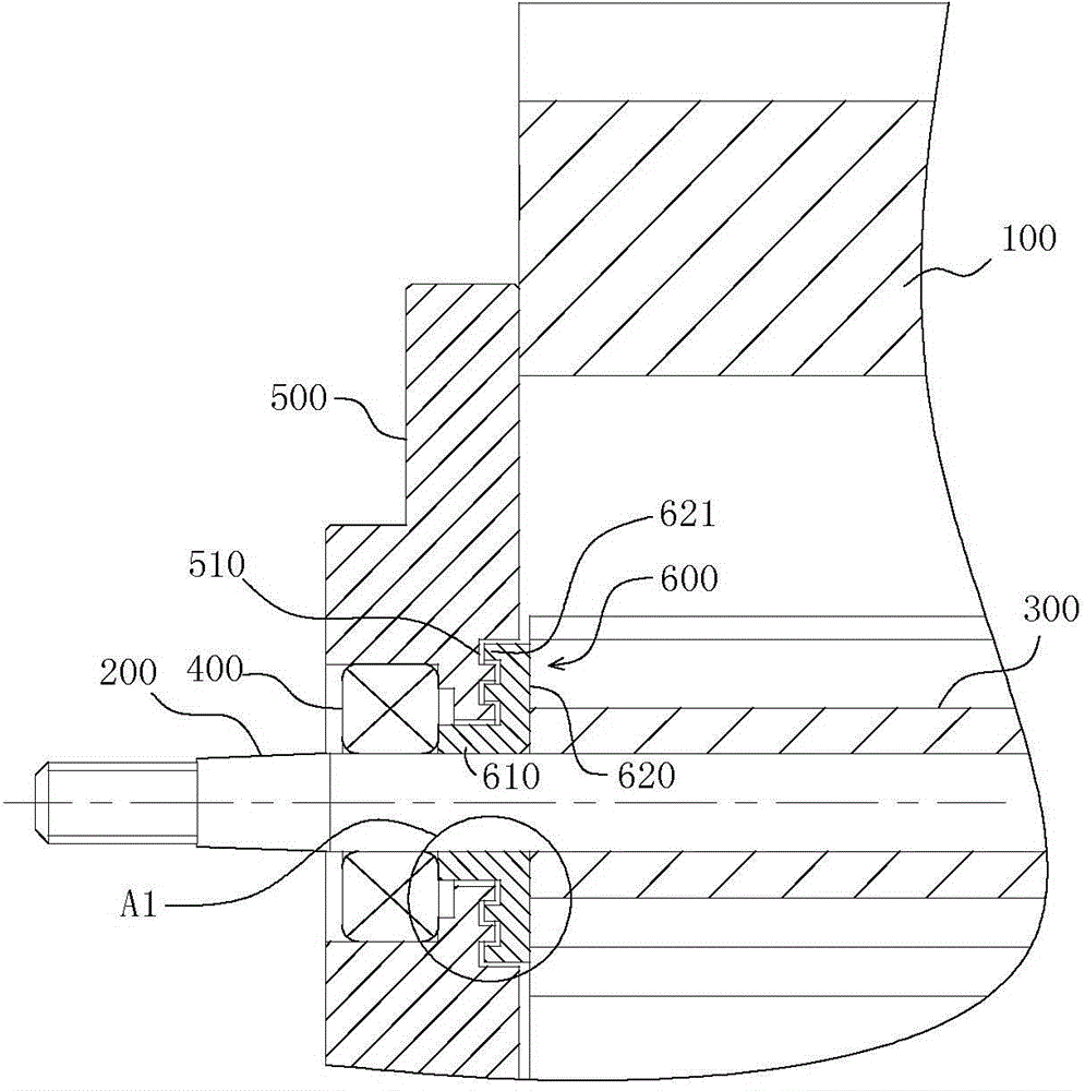
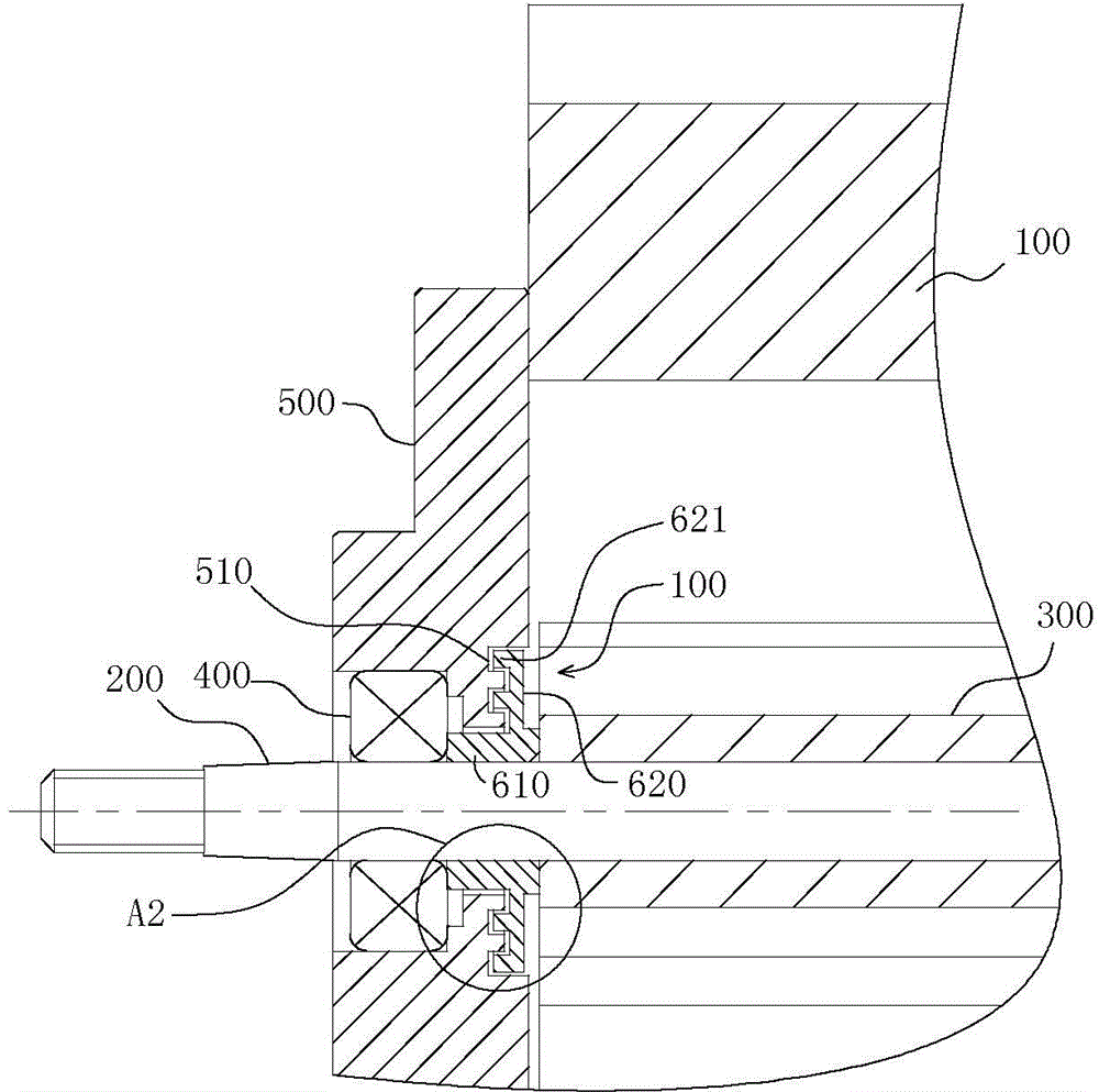
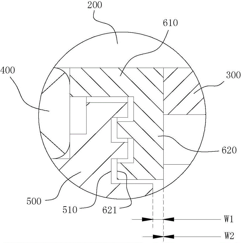
[0012] figure 1 , 3 As shown, the Roots gas flowmeter of Embodiment 1 of the present invention includes a housing 100, a mandrel 200 and a Roots wheel 300, the mandrel 200 is connected to the housing 100 through a bearing 400, and the Roots wheel 300 is installed on the mandrel 200 and set in the housing 100, the side of the housing 100 is also equipped with a pressure plate 500, the bearing 400 is installed on the pressure plate 500, the inner surface of the pressure plate 500 and the end surface of the Roots wheel 300 opposite to the inner surface A first side gap is formed between them, and the width W1 of the first side gap is 0.15 mm; the mandrel 200 is covered with a dust-proof spacer 600, and the dust-proof spacer 600 has a shaft sleeve part 610 and is located on the shaft sleeve part 610. The convex ring portion 620 on the outer cylindrical surface, the sleeve portion 610 is matched with the shaft of the mandrel 200 and the front and rear ends of the sleeve portion 61...


PUM


Abstract

The invention discloses a Roots gas flowmeter. The Roots gas flowmeter has the advantage that the condition that dust in metered gas enters a bearing and then affects metering accuracy can be prevented. According to the Roots gas flowmeter, a pressing plate is mounted at the side part of a shell body of the Roots gas flowmeter, the bearing is mounted on the pressing plate, a first side gap is formed between the inner side face of the pressing plate and the end face, opposite to the inner side face, of a Roots wheel, and the width of the first side gap is greater than 0mm and not greater than 0.35mm; a dustproof spacing ring sleeves on a core shaft and is provided with a shaft sleeve part and a convex ring part which is located on an external cylindrical face of the shaft sleeve part, the shaft sleeve part is in shaft fit with a core shaft hole, the front and rear ends of the shaft sleeve part are respectively abutted against opposite end faces of the bearing and the Roots wheel, also, the dustproof spacing ring is fixedly arranged between the bearing and the Roots wheel axially, at least two circles of annular sealing teeth, which are arranged along the radial direction of the convex ring part at intervals and take the central axis of the core shaft as a circle center, are formed in one side face, facing to the pressing plate, of the upper face of the convex ring part, the pressing plate and the dustproof spacing ring are in non-contact fit, and sealing tooth grooves, which form complicated labyrinthine gaps with the annular sealing teeth, are formed in the pressing plate.

Description

technical field [0001] The invention relates to a gas flowmeter, in particular to a Roots gas flowmeter. Background technique [0002] In the gas transmission and distribution industry, Roots gas flow meters are widely used high-precision measuring instruments. The Roots gas flowmeter currently in use mainly includes a shell, a mandrel and a Roots wheel. The mandrel is connected to the shell through a bearing. There is also a certain sealing structure between the shell and the shell to prevent gas from leaking out. The inventor has found through research and analysis that the above-mentioned Roots gas flowmeter has a shortcoming that has been neglected for a long time: because the gas (such as natural gas) passing through the Roots flowmeter often contains a certain amount of dust, and the Roots gas flowmeter There is no structure in the meter that can effectively block these dusts from intruding into the bearing, so the rotation flexibility of the bearing will decrease af...

Claims


Application Information

Patent Timeline
Patent Type & Authority Applications(China)
IPC IPC(8): G01F11/28
Inventor 向勇谢贤伟游米富
Owner CHENGDU LUNCI INSTR
Why Eureka
Try Eureka