Multi-View Display

A multi-view field display and display module technology, which is applied in the directions of instruments, optics, electrical components, etc., and can solve problems such as resolution reduction.

Active Publication Date: 2016-08-24
AU OPTRONICS CORP
View PDF7 Cites 0 Cited by
  • Summary
  • Abstract
  • Description
  • Claims
  • Application Information

AI Technical Summary

Problems solved by technology

[0004] There are many ways to design 3D stereoscopic TV, but in any case, when distributing pixels to multiple viewing fields, the resolution will also be reduced at the same time

Method used


Image

  • Multi-View Display
  • Multi-View Display
  • Multi-View Display

Examples


Embodiment Construction

[0082] Hereinafter, multiple embodiments of the present invention will be disclosed with the accompanying drawings. For clear description, many practical details will be described in the following description. However, it should be understood that these practical details should not be used to limit the present invention. In other words, in some embodiments of the present invention, these practical details are unnecessary. In addition, in order to simplify the drawings, some conventionally used structures and elements will be shown in the drawings in a simple schematic manner.

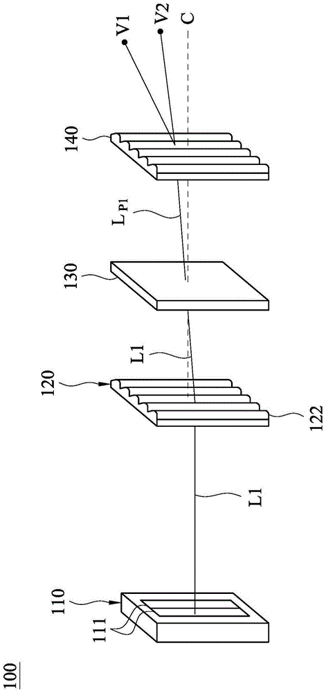
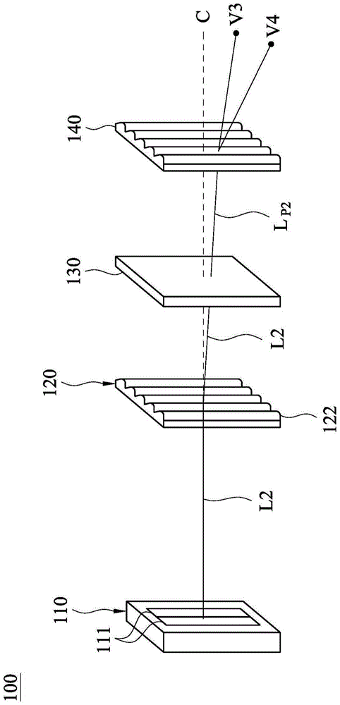
[0083] Please also refer to Figure 1A versus Figure 1B ,among them Figure 1A Shows an exploded schematic diagram of the multi-view zone display 100 in the first time sequence according to an embodiment of the present invention, Figure 1B Illustrate Figure 1A An exploded schematic diagram of the multi-view zone display 100 in the second time sequence. The multi-view area display 100 of this embodiment in...


PUM


Abstract

The present invention provides a multi-view display, comprising a light source module, a first lenticular lens array, a display module and a second lenticular lens array, the light source module is used to provide multiple light rays in sequence, and the first lenticular lens array is arranged in front of the light source module , to guide the light from the light source module to advance in multiple directions, the display module is arranged in front of the first lenticular lens array, and is used to convert the light from the first lenticular lens array into a plurality of pixel light respectively, and the second The lenticular lens array is arranged in front of the display module, and is used to respectively guide the pixel light to a plurality of viewing areas. The multi-view display provided by the present invention increases the view fields that can be generated by the multi-view display in one cycle, thereby reducing the decrease in resolution when the number of view fields increases.

Description

Technical field [0001] The invention relates to a multi-view area display, in particular to a multi-view area display that can be recognized by naked eyes. Background technique [0002] Because the position of the left eye and the right eye are different, the scenes they observe are also slightly different. This difference is the root cause of the stereoscopic effect. 3D stereo TV uses the visual characteristics of the eye to produce the stereoscopic effect. [0003] The traditional way to achieve a three-dimensional effect is to use spatial multiplexing, that is, pixels on the screen are assigned multiple view information, and the light splitting effect of the lens converges at the viewing distance to generate multiple views. The person corresponds to two of the viewing areas, so that the two eyes correspond to different images to achieve a 3D visual effect [0004] There are many methods for 3D stereo TV design, but in any case, when pixels are allocated to multiple fields of view...

Claims


Application Information

Patent Timeline
Patent Type & Authority Patents(China)
IPC IPC(8): G02B27/26H04N13/04G02B30/25G02B30/27
CPCG02F1/1347G02F1/133526G02F1/133528G02B30/25G02B30/27G02F1/133562G02F1/133567
Inventor 王智杰施志昌
Owner AU OPTRONICS CORP
Why Eureka
Try Eureka