
Touch screen touch area positioning method

A technology of touch area and positioning method, which is applied in the direction of instruments, electrical digital data processing, and input/output process of data processing, etc., can solve the problems of long time consumption, achieve the effects of saving time, narrowing the judgment range, and improving recognition efficiency

Active Publication Date: 2014-08-13
HUZHOU ZAAG ELECTRIC TECH
View PDF8 Cites 18 Cited by
  • Summary
  • Abstract
  • Description
  • Claims
  • Application Information

AI Technical Summary

Problems solved by technology

[0002] The multi-point identification and positioning method in the prior art, such as the multi-point identification method and system of an infrared touch screen disclosed in the invention patent application with the application publication number of CN102419662A, first generates an axis corresponding to the axis of the infrared touch screen in one identification process. axis image; then extract the touch point information in the axis image; however, in this recognition method based on image processing, the determination of the touch point needs to be processed globally, so it takes a long time

Method used


Image

  • Touch screen touch area positioning method
  • Touch screen touch area positioning method
  • Touch screen touch area positioning method

Examples


Embodiment 1

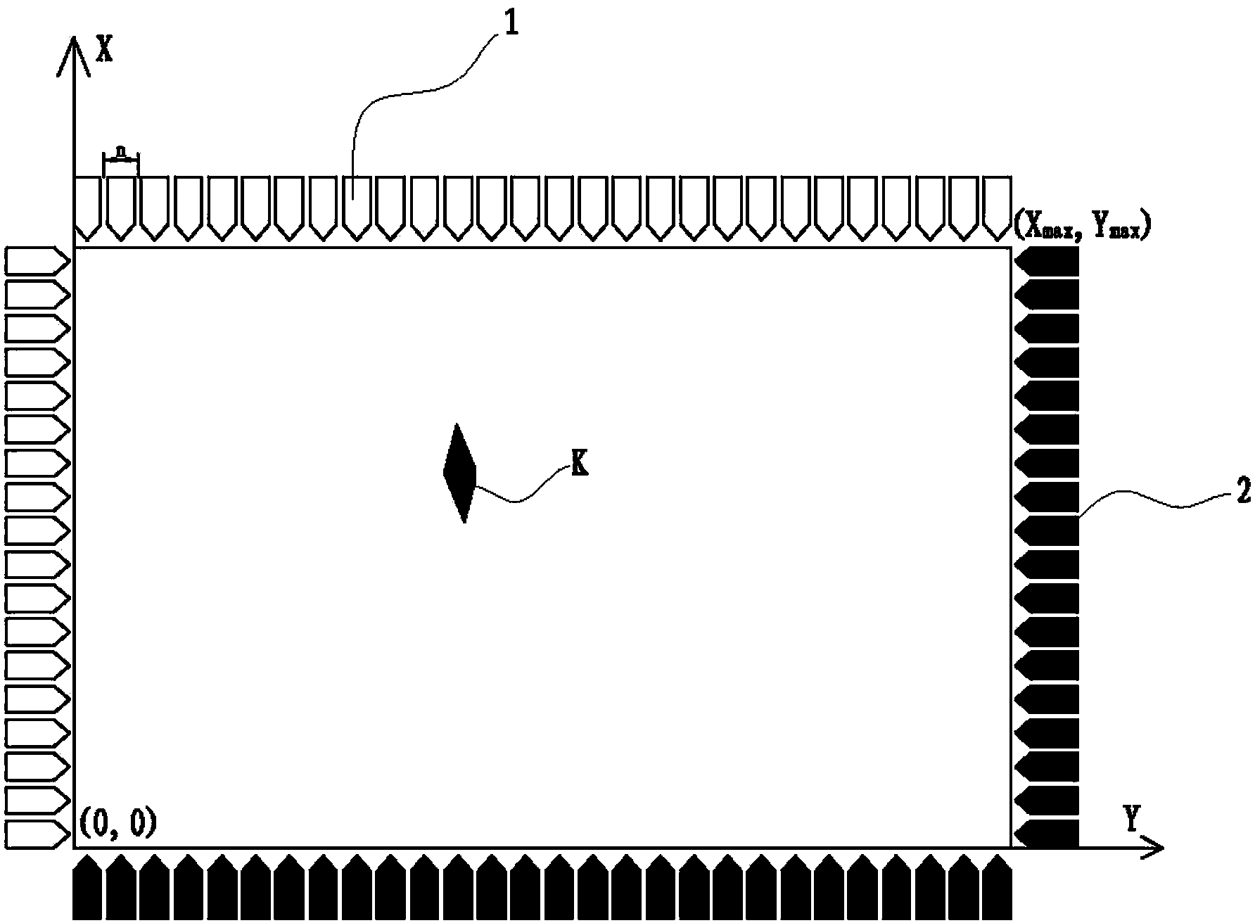
[0024] Embodiment 1: as figure 1 As shown, the four sides of the touch screen are respectively provided with an infrared emitting element 1 and an infrared receiving element 2 .

[0025] Assume that an optical path from one infrared emitting element 1 to one infrared receiving element 2 is a unit optical path.

[0026] Taking the infrared emitting element 1 as the starting point of the optical path, and the infrared receiving element 2 as the end point of the optical path, the optical width of the starting point of the optical path determined by each infrared emitting element 1 should be equal to the optical width of the end point of the optical path determined by each infrared receiving element 2, assuming The light width of the starting point of the light path determined by each infrared emitting element 1 is the unit light width.

[0027] According to the resolution of the touch screen, determine the unit light width as n; thus establish a coordinate XY system, such as fi...

Embodiment 2

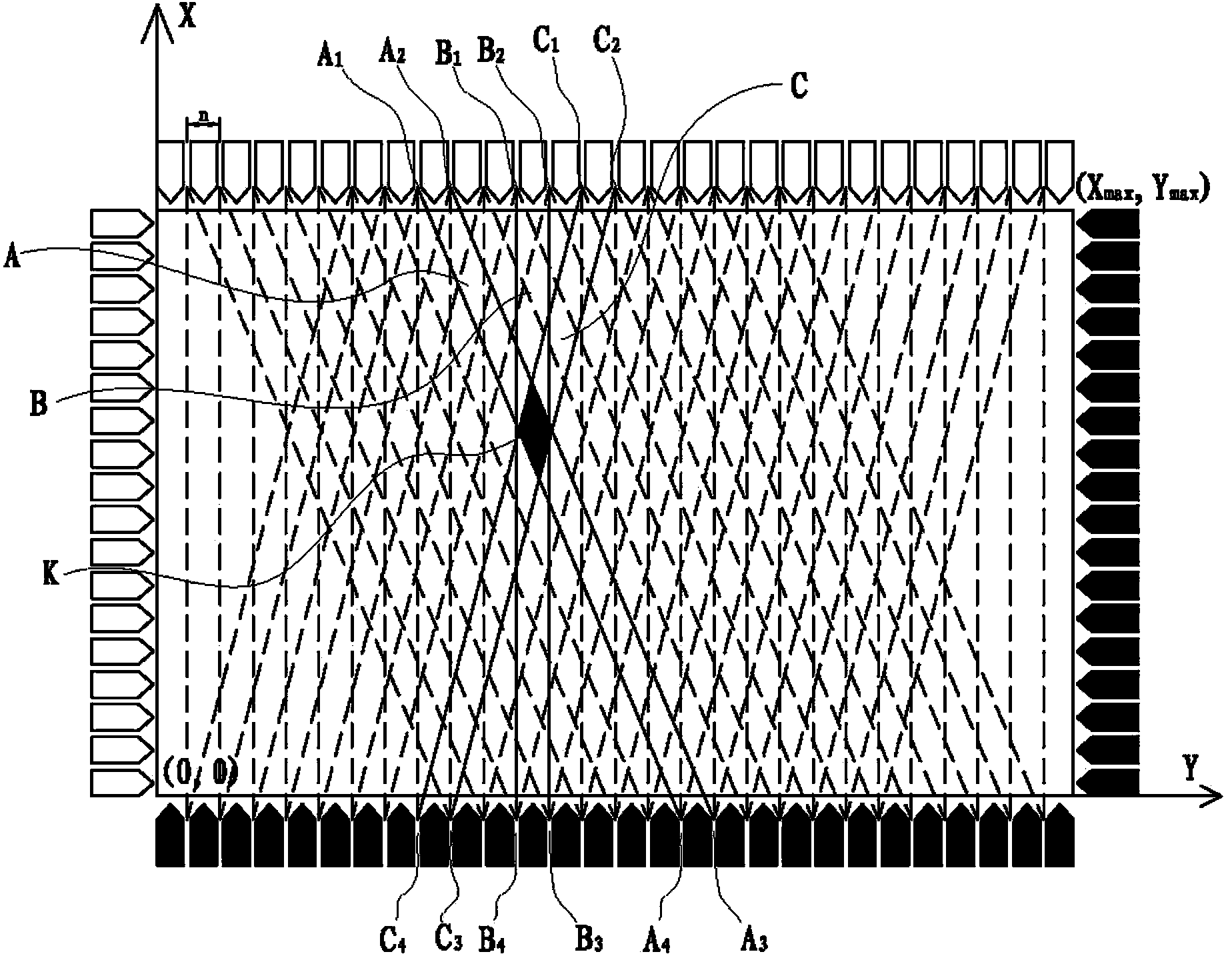
[0061] Embodiment 2: as figure 1 As shown, the area K where the touch area occurs, the identification steps of the area K are as follows,

[0062] (1) In one frame, scan all optical path layers, and figure 2 In , the dotted line and the solid line at the same angle represent a layer of optical path, and all blocked unit optical paths are obtained. There are three unit optical paths, namely A, B, and C, such as figure 2 The solid line area in the middle, and obtain the coordinates of the three light paths, that is, the four vertices of the light path A are A 1 (X a1 , Y a1 ), A 2 (X a2 , Y a2 ), A 3 (X a3 , Y a3 ), A 4 (X a4 , Y a4 ), since the three light paths are unit light paths, X a2 -X a1 = n, Y a1 =Y a2 =Y max , X a3 -X a4 = n, Y a3 =Y a4 =0;

[0063] The four vertices of light path B are B 1 (X b1 , Y b1 ), B 2 (X b2 , Y b2 ), B 3 (X b3 , Y b3 ), B 4 (X b4 , Y b4 ), since the three light paths are unit light paths, X b2 -X b1 = n, Y...

Embodiment 3

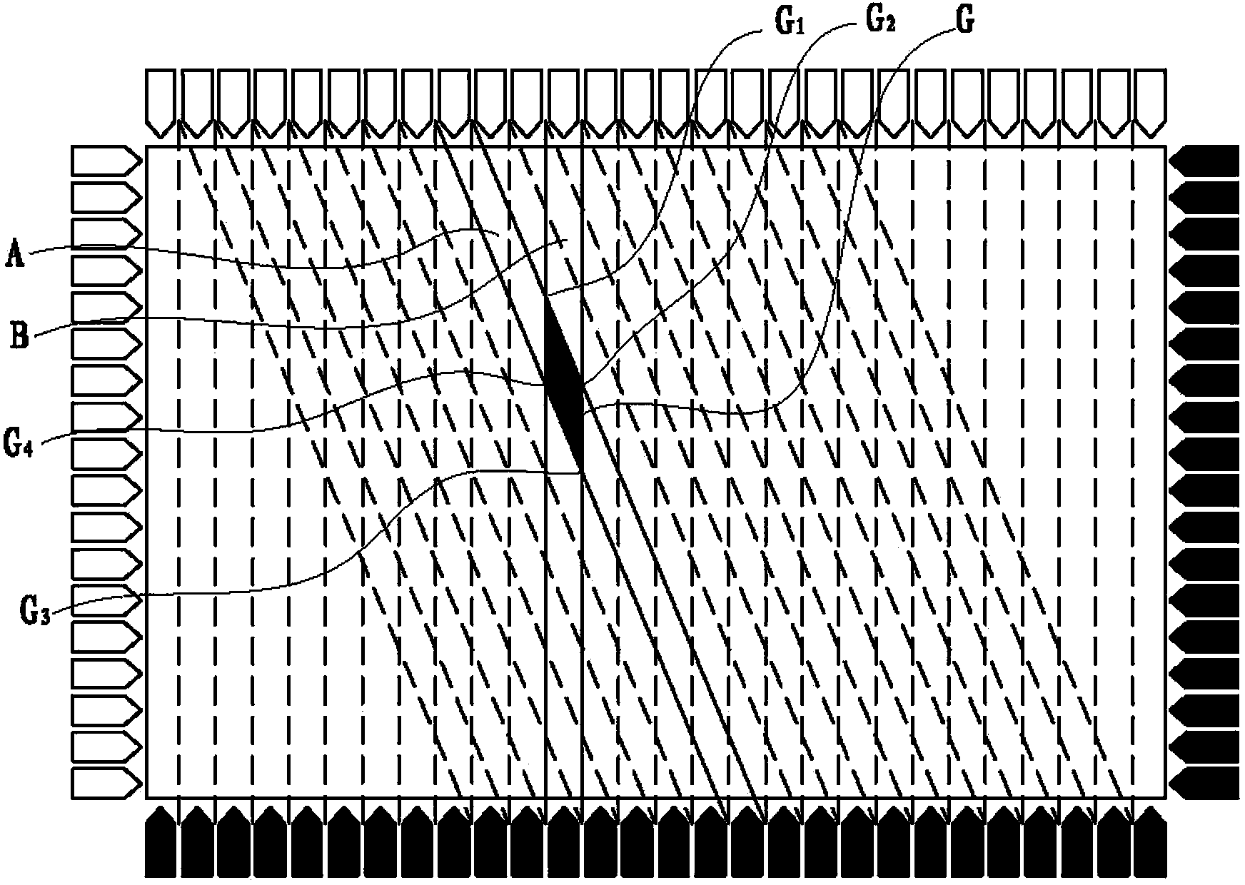
[0068] Embodiment 3: Generating at least two touch points at the same time, the recognition method is similar to Embodiment 1, except that when calculating the polygon result coordinates, two or more polygon result coordinates are calculated at the same time.


PUM


Abstract

The invention relates to the technique of touch screens, in particular to a touch screen touch area positioning method. According to the technical scheme, the touch screen touch area positioning method includes the following steps that (1) all blocked light paths are obtained; (2) the blocked light paths are converted into polygonal data; (3) if a set of the light paths at the same angle is a light path layer, a polygon in one light path layer is intersected with a polygon in another light path layer, a new polygon is obtained, then the new polygon is intersected with the polygon in another light path layer to obtain a new polygon, the process is repeated until the polygons of all light path layers are intersected, an ultimate polygon is obtained and at least comprises one polygon body, and data of the ultimate polygon are recorded and comprise data of all polygon bodies. Identification of a touch area takes little time and is high in efficiency.

Description

technical field [0001] The invention relates to touch screen technology, in particular to a method for locating a touch area of ​​a touch screen. Background technique [0002] The multi-point identification and positioning method in the prior art, such as the multi-point identification method and system of an infrared touch screen disclosed in the invention patent application with the application publication number of CN102419662A, first generates an axis corresponding to the axis of the infrared touch screen in one identification process. The axis image; then extract the touch point information from the axis image; however, in this recognition method based on image processing, the determination of the touch point needs to be processed globally, so it takes a long time. Contents of the invention [0003] The purpose of the present invention is to provide a method for locating a touch area of ​​a touch screen, which takes less time to identify the touch area and has high ef...

Claims


Application Information

Patent Timeline
Patent Type & Authority Applications(China)
IPC IPC(8): G06F3/042
CPCG06F3/0421G06F3/042
Inventor 王迪李金鹏齐洋
Owner HUZHOU ZAAG ELECTRIC TECH
Learn More