
A Modeling Method for Complex Equipment System

A modeling method and equipment technology, applied in special data processing applications, instruments, electrical digital data processing, etc., can solve problems such as low system reuse efficiency, lack of correlation of views, and model inconsistency, so as to improve design efficiency and ensure Effects of Design Quality, Efficient Concurrent Design

Active Publication Date: 2017-09-05
燕雪峰
View PDF5 Cites 1 Cited by
  • Summary
  • Abstract
  • Description
  • Claims
  • Application Information

AI Technical Summary

Problems solved by technology

Such a result ignores business requirements, resulting in a disconnect between business requirements and system design, directly affecting the design quality of the model
[0006] 2. System reuse efficiency is low
The development trend of the equipment system is based on the common business process as the center and starting point. Although the traditional equipment-based system construction method can support system reuse at the component level, the system upgrade efficiency is low and the cycle is long due to the granularity of reuse.
[0007] 3. It is difficult to continuously optimize the model, and does not fully support parallel iterative design
Although the traditional use-case-driven method supports iterative design, it is mainly based on use cases and is out of touch with the business process, resulting in the division of labor and overlapping of design teams in different fields. The quality of the designed system model is poor, and continuous optimization cannot be performed.
[0008] 4. Lack of consistency checks between models
Traditional system modeling methods start directly from requirement analysis and build multiple views separately. The lack of correlation between views leads to design defects such as model inconsistency
[0009] 5. Human-computer interaction design is decentralized
Different businesses in the system are often designed and developed by different teams, resulting in inconsistent display and operation styles
[0010] 6. It is difficult to realize the dynamic reorganization of business process functions
Existing equipment system design methods require relatively stable system functions and do not support dynamic reorganization of business process functions

Method used


Image

  • A Modeling Method for Complex Equipment System

Examples


Embodiment 1

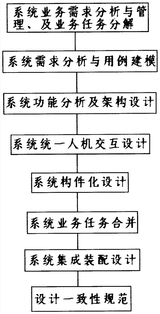
[0119] The following will take the helicopter control system as an example to further describe the technical solution of the present invention in detail: according to the business process-driven design concept, its goal is to assist the design team to carry out system business demand analysis, system demand analysis, and system function analysis in parallel or iteratively , architecture design, unified human-computer interaction design, component design and integrated assembly design. Through the definition and specification of the whole life cycle design activities, the integration of requirements analysis, system design and application integration is truly realized, so as to improve design efficiency, ensure design quality, and give full play to the comprehensive advantages of the system.

[0120] (1) Analysis and management of X-type helicopter control system business requirements, and business task decomposition:

[0121] a. Document X-Helicopter Control System Mission Requi...


PUM


Abstract

The invention discloses a modeling method of a complex equipment system. According to the method, the analysis of the complex equipment system is defined; the activities, the specifications and the interfaces of each link, and adopted models and views are designed; the design efficiency is improved, and the design quality is guaranteed; the concurrent design of the system can be performed by a design team orderly and effectively.

Description

technical field [0001] The invention relates to a modeling method, in particular to a modeling method of a complex equipment system. Background technique [0002] In recent years, in order to cope with the increasingly fierce competition and challenges of globalization, all walks of life are improving their competitiveness through continuous strategic adjustments, business reorganizations, and management reforms. The traditional system engineering method emphasizes the system construction method based on functional decomposition, which cannot meet the needs of continuous improvement of the system business process. In recent years, although the use-case-driven, domain-oriented, and component-based system design and development ideas have become more and more popular, which has alleviated the contradiction to a certain extent, how to dynamically support business reorganization, extract system functions from business requirements, and implement functions and components? Seamle...

Claims


Application Information

Patent Timeline
Patent Type & Authority Patents(China)
IPC IPC(8): G06F17/50
Inventor 燕雪峰高暠周勇
Owner 燕雪峰
Learn More