Check patentability & draft patents in minutes with Patsnap Eureka AI!

Mold fixer of slipform paver

A slip-form paver and fixer technology, which is applied in roads, road repairs, roads, etc., can solve the problems that the inclination angle of the mold cannot be automatically adjusted, it is difficult to adapt to road construction, and the efficiency of replacing and installing the mold is low, so as to achieve high efficiency and speed Replacement and installation, fast and easy replacement, and simple structure

Active Publication Date: 2014-08-20
山东万顺机械制造有限公司
View PDF7 Cites 1 Cited by
  • Summary
  • Abstract
  • Description
  • Claims
  • Application Information

AI Technical Summary

Problems solved by technology

[0002] The sliding form mold of the existing paver is connected and fixed by a pin shaft, and the mold is connected with a single cylinder. This method cannot automatically adjust the inclination angle of the mold during construction; when removing the mold, it must be placed on the ground first, and then pulled Lower the pin shaft, and finally move the main body of the paver to separate the molds. It is difficult to adapt to road construction with frequent changes in paving molds, and the efficiency of replacing and installing molds is low.

Method used


Image

  • Mold fixer of slipform paver
  • Mold fixer of slipform paver
  • Mold fixer of slipform paver

Examples


Embodiment 1

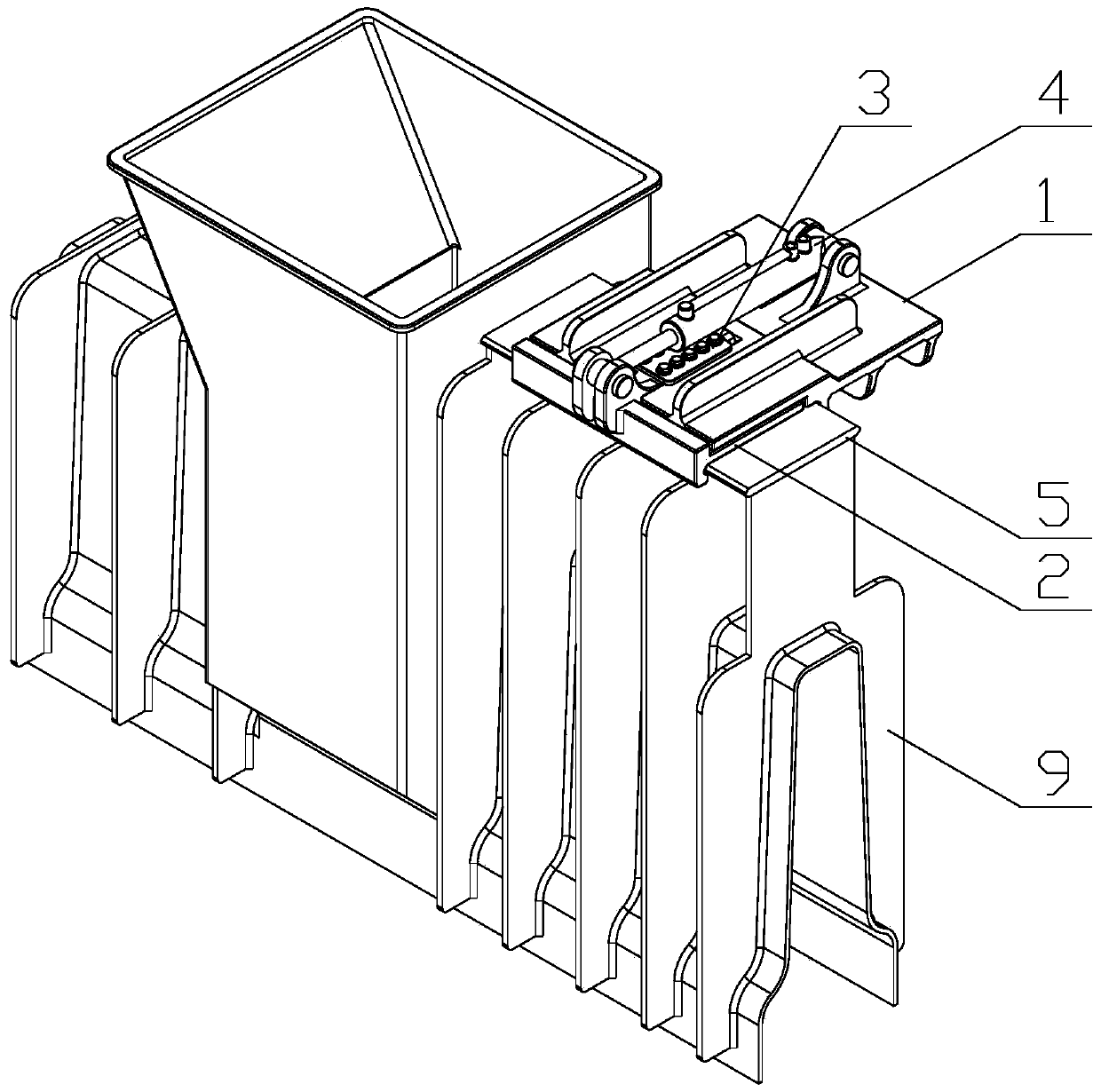
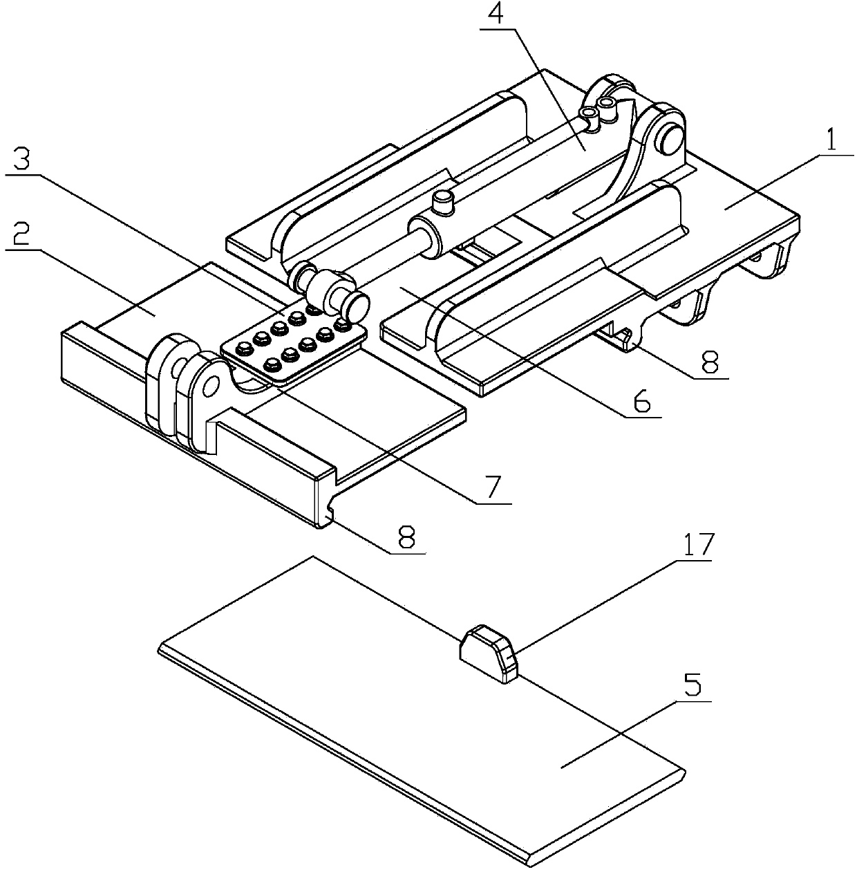
[0014] Embodiment 1: as figure 1 with figure 2 As shown, the slipform paver mold holder includes a holder bottom plate 1, a movable splint 2, a splint limit block 3, a holder oil cylinder 4, and a sliding form connecting plate 5; Slideway 6 is provided with a limit slide 7 at the top of the movable splint 2, and the limit slide 7 is slidably inserted in the slideway 6, and the top surface of one end of the movable splint 2 is in sliding contact with the bottom surface of the holder base plate 1; The top surface of the slide table 7 is provided with a splint limit block 3, and the bottom surface of the splint limit block 3 is in sliding contact with the top surface of the holder base plate 1; The top of the piston rod of the oil cylinder 4 is connected with the top of the movable splint 2 through a pin shaft; through the expansion and contraction of the fixer oil cylinder 4, the limit slide 7 of the movable splint 2 slides along the slideway 6, and the splint on the limit sli...

Embodiment 2

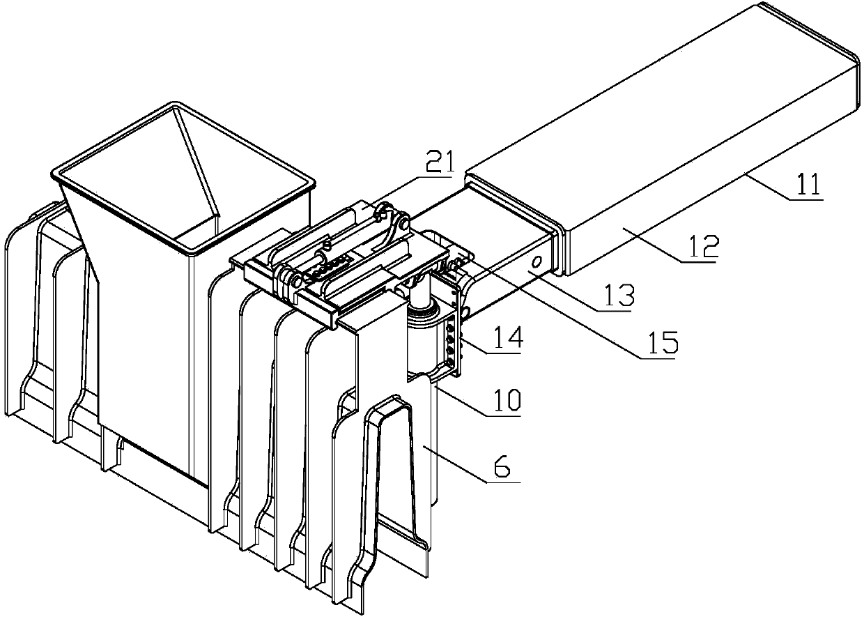
[0015] Embodiment 2: as image 3 As shown, the mold holder for a slipform paver includes a holder base plate 1, a movable splint 2, a splint limit block 3, a holder cylinder 4, a sliding form connecting plate 5, two lifting cylinders 10 and a horizontal telescopic support 11 ;Such as figure 1 As shown, a slideway 6 is provided at one end of the fixture bottom plate 1, and a limit slide 7 is provided at the top of the movable splint 2, and the limit slide 7 is slidably inserted in the slideway 6, and the top surface of the movable splint 2 is It is in sliding contact with the bottom surface of the holder bottom plate 1; a splint limit block 3 is provided on the top surface of the limit slide table 7, and the bottom surface of the splint limit block 3 is in sliding contact with the top surface of the holder bottom plate 1; the cylinder body of the holder oil cylinder 4 It is connected with the top of the holder bottom plate 1 through a pin shaft, and the top of the piston rod o...


PUM


Abstract

A disclosed mold fixer of a slipform paver comprises a fixer bottom plate, a mobile clamping plate, a clamping-plate limit block, a fixer oil cylinder and a slipform connection plate; one side end of the fixer bottom plate is provided with a slideway; the top of the mobile clamping plate is provided with a limit slide table, and the limit slide table is inserted into the slideway in a sliding way; the top surface of the limit slide table is provided with the clamping-plate limit block; the cylinder body of the fixer oil cylinder is connected with the top of the fixer bottom plate via a pin; the top end of the piston rod of the fixer oil cylinder is connected with the top of the mobile clamping plate via a pin; the outer end of the mobile clamping plate and the bottom of the fixer bottom plate are respectively correspondingly provided with a vertically-downward clamping part; and the slipform connection plate is flexibly arranged between the two clamping parts and is connected with a slipform mold. The mold fixer has the advantages that hydraulic pressure is employed for mounting and dismounting a mode when the mole is installed or replaced, also the automatic positioning function and the tightly-clamping function are provided, so that replacing of the mold is rapid and easy, efficient rapid replacing and installation are realized, and maximum convenience is provided for frequently-converted paving engineering.

Description

Technical field: [0001] The invention relates to a pair of supporting equipment for a slip-form paver, in particular to a die fixer for a slip-form paver. Background technique: [0002] The sliding form mold of the existing paver is connected and fixed by a pin shaft, and the mold is connected with a single cylinder. This method cannot automatically adjust the inclination angle of the mold during construction; when removing the mold, it must be placed on the ground first, and then pulled Lower the pin shaft, and finally move the main body of the paver to separate the molds. It is difficult to adapt to the road construction where the paving molds are frequently changed, and the efficiency of replacing and installing the molds is low. Invention content: [0003] The object of the present invention is to provide a high-efficiency and fast-changing mold holder for a slip-form paver. [0004] The present invention is implemented by the following technical scheme: a mold holder...

Claims


Application Information

Patent Timeline
Patent Type & Authority Applications(China)
IPC IPC(8): E01C19/48
Inventor 陈建军
Owner 山东万顺机械制造有限公司
Features
  • R&D
  • Intellectual Property
  • Life Sciences
  • Materials
  • Tech Scout
  • Unparalleled Data Quality
  • Higher Quality Content
  • 60% Fewer Hallucinations
Learn More