
A Termination Structure for Improving Avalanche Tolerance of Superjunction Power Devices
A terminal structure, avalanche tolerance technology, applied in semiconductor devices, electrical components, thyristors, etc., can solve problems such as poor avalanche tolerance, improve reliability, avoid parasitic BJT conduction problems, and avoid the effect of long avalanche current paths
- Summary
- Abstract
- Description
- Claims
- Application Information
AI Technical Summary
Problems solved by technology
Method used
Image

Examples
Embodiment Construction
[0023] Below in conjunction with accompanying drawing and embodiment, describe technical solution of the present invention in detail:
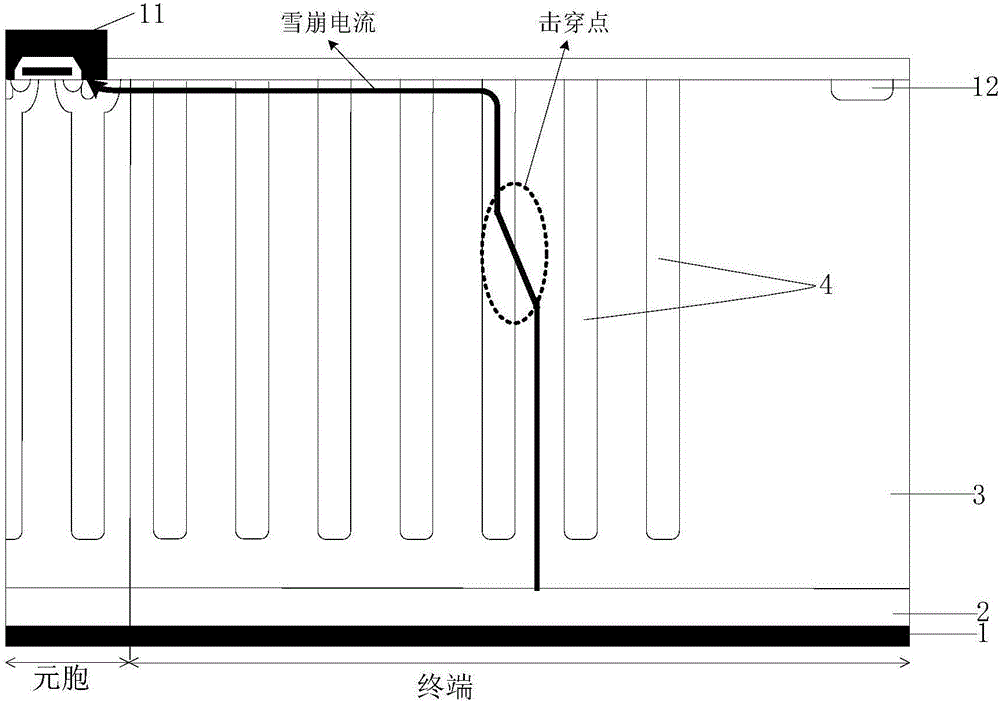
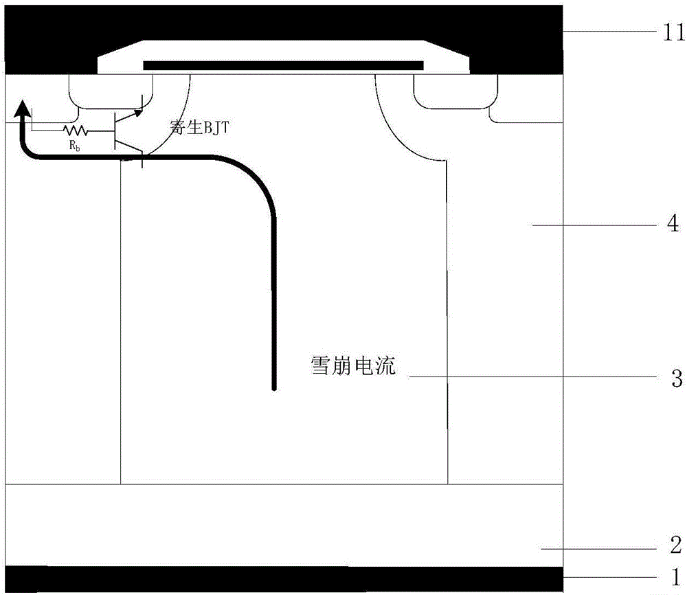
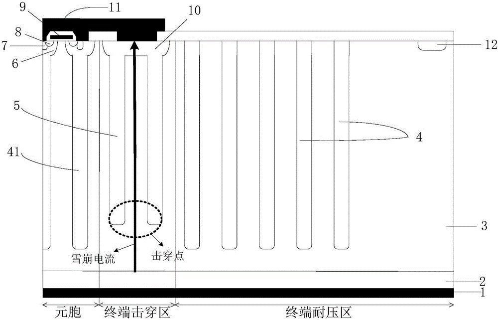
[0024] Such as figure 1 As shown, it is a schematic diagram of the terminal structure of a common super-junction MOSFET. When the avalanche breakdown of the device occurs at the terminal, the location of the breakdown point is random, and the avalanche current will flow from the breakdown point through the terminal surface to the source of the device. The farther the breakdown point is from the element cells, the longer the path of the avalanche current flows. Figure 4 This is the distribution diagram of the avalanche current at the terminal of a common super-junction MOSFET obtained by the simulation tools Tsuprem4 and Medic. It can be seen from the figure that the avalanche current will flow laterally through the surface of the terminal with a long path. The longer the avalanche current path, the greater the resistance of the avalanche cur...
PUM
 Abstract
Description
Claims
Application Information