Rotor feeding device

A technology of feeding device and rotor, which is used in the manufacture of stator/rotor body, etc., can solve the problems of the influence of assembly line production, slippery jam, easy jamming, etc., and achieves the effect of ensuring normal transfer and preventing jamming.

Active Publication Date: 2014-08-20
合肥凯邦电机有限公司
View PDF4 Cites 7 Cited by
  • Summary
  • Abstract
  • Description
  • Claims
  • Application Information

AI Technical Summary

Problems solved by technology

combined with figure 1 As shown, the retaining ring B is in the shape of a ring with an opening, and because there is always a difference in linear velocity during the rolling of the shaft at both ends of the rotor core A, when the rotor slides on a long slide, the retaining ring The opening of B is easy to be stuck at the upper end of the support plate, and the rotor is easy to cause material jamming on the slideway, which will affect the production of the assembly line

Method used


Image

  • Rotor feeding device
  • Rotor feeding device
  • Rotor feeding device

Examples


Embodiment Construction

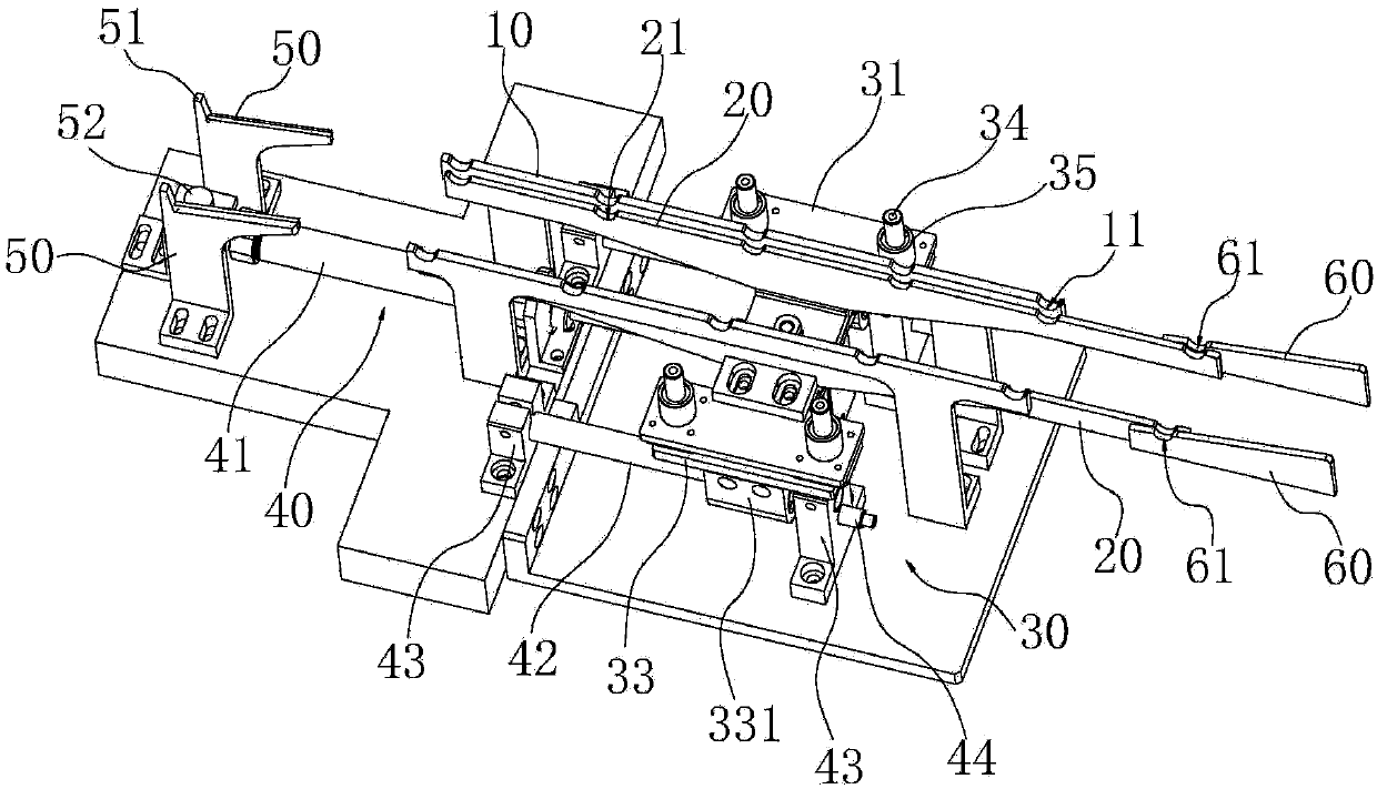
[0013] Combine below Figure 1 to Figure 9 , the present invention is further described:

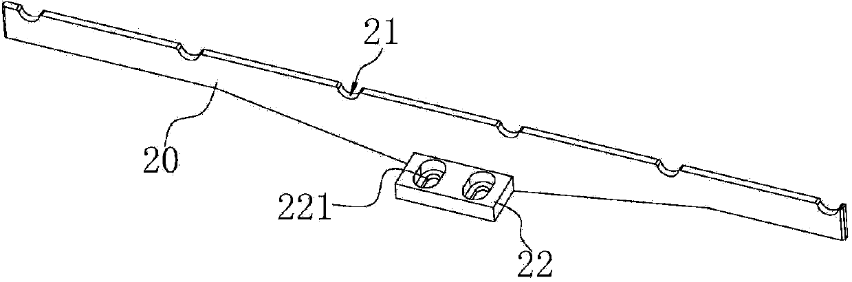
[0014] A rotor feeding device, comprising two supporting frames 10 arranged at intervals on the machine base, the upper ends of the two supporting frames 10 are correspondingly provided with positioning grooves 11, the device also includes two moving frames 20 arranged at intervals, the moving The length direction of the frame 20 is parallel to the length direction of the support frame 10 and the upper end is provided with a card slot 21. The mobile frame 20 is arranged on the lifting unit 30, and the lifting unit 30 drives the mobile frame 20 to present the card slot 21 when it is lifted to the highest position. The bottom is higher than the upper end surface of the support frame 10 and the upper end surface of the mobile frame 20 is lower than the bottom of the positioning groove 11 of the support frame 10 when it is lowered to the lowest position. The mobile frame 20 is also connected...


PUM


Abstract

The invention belongs to the field of motor production, and particularly relates to a rotor feeding device. The rotor feeding device comprises two supporting frames arranged on a machine base in a spaced mode. The upper ends of the two supporting frames are provided with positioning grooves correspondingly. The motor feeding device further comprises two movable frames arranged in a spaced mode. The length direction of the movable frames is parallel to the length direction of the supporting frames, and the upper ends of the movable frames are provided with clamping grooves. The movable frames are arranged on a lifting unit. The lifting unit drives the movable frames to achieve two position states. According to one position state, when the movable frames are driven to ascend to the highest position, the bottoms of the clamping grooves are higher than the upper end faces of the supporting frames. According to the other position state, when the movable frames are driven to descend to the lowest position, the upper end faces of the movable frames are lower than the bottom of the positioning grooves of the supporting frames. The movable frames are further connected with a transportation unit. The transportation unit drives the movable frames to displace in the horizontal direction, and the positioning grooves and the clamping grooves are in the staggered position or the same position. A rotor is transported from one position to the other position by utilizing the clamping grooves and the positioning grooves, rotating shafts at the two ends of a rotor iron core are accurately positioned, the phenomenon of material clamping in the rotor transportation process is fundamentally and completely eradicated, and it is ensured that the rotor can be normally transported.

Description

technical field [0001] The invention belongs to the field of motor production, in particular to a rotor feeding device. Background technique [0002] During the assembly process of the rotating shaft of the motor rotor and the bearing, it is necessary to install a retaining ring on the rotating shaft of the rotor, and use the retaining ring to cooperate with the inner ring of the bearing to limit the axial movement of the bearing on the rotating shaft. In the current production of the enterprise, the rotor assembled with the retaining ring is set on the slideway. The slideway is two vertical support plates arranged at intervals. The upper edge of the support plate is arranged obliquely. On the two support plates, the rotating shafts at both ends of the rotor core roll along the upper edge of the support plate, so that the rotor can be moved from one position to another on the assembly line to realize the production and assembly of the motor in each process. combined with f...

Claims


Application Information

Patent Timeline
Patent Type & Authority Applications(China)
IPC IPC(8): H02K15/02
Inventor 陆卫
Owner 合肥凯邦电机有限公司
Why Eureka
Try Eureka