An optical signal identification and detection method and device

A detection method and optical signal technology, applied in the field of optical communication transmission, can solve problems such as unsatisfactory requirements and limited frequency identification of all-optical networks

Active Publication Date: 2017-12-29
FENGHUO COMM SCI & TECH CO LTD
View PDF4 Cites 0 Cited by
  • Summary
  • Abstract
  • Description
  • Claims
  • Application Information

AI Technical Summary

Problems solved by technology

[0005] The technical problem to be solved by the present invention is that the available frequency identification of the all-optical network is limited and cannot meet the demand

Method used


Image

  • An optical signal identification and detection method and device
  • An optical signal identification and detection method and device
  • An optical signal identification and detection method and device

Examples


Embodiment Construction

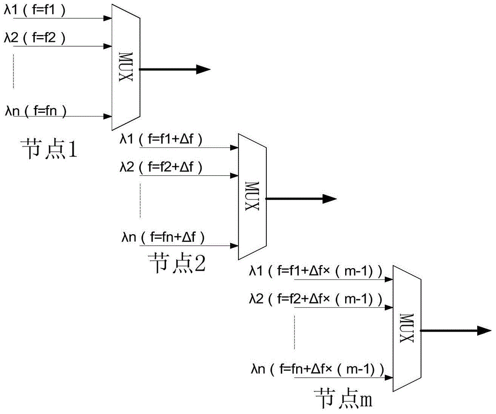
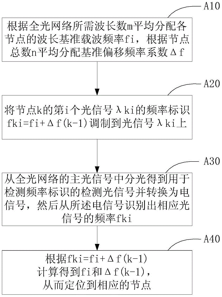
[0026] The optical signal identification and detection method and device provided by the present invention use a combination of wavelength reference carrier frequency and node reference offset frequency to carry out wavelength identification on different nodes, and allocate different carrier frequency intervals for optical signals of different wavelengths, effectively greatly expands the number of available frequency identifiers. The present invention will be further described in detail below in conjunction with the accompanying drawings.

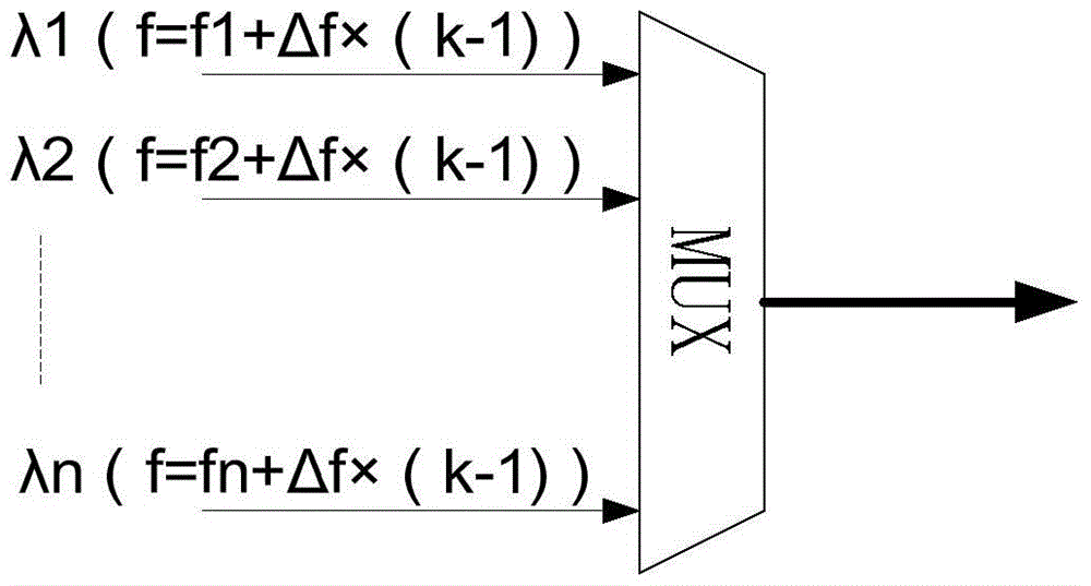
[0027] figure 1 It is a schematic diagram of frequency identification of n different wavelengths λ1...λn in the same node k in the present invention. For the same node k, different wavelengths are identified by a combination of different wavelength reference carrier frequencies and the same node reference offset frequency Δf×(k-1). For example, the reference carrier frequency of the wavelength λ1 of the first optical signal is f1, and The...


PUM


Abstract

The present invention relates to a method and device for identifying and detecting optical signals. The method comprises the following steps: according to the number m of wavelengths required by the all-optical network, the wavelength reference carrier frequency fi of each node is evenly distributed, and according to the total number of nodes n, the reference offset is distributed evenly Frequency coefficient Δf, i=1~m; the frequency identification fki=fi+Δf(k-1) of the i-th optical signal λki of node k is modulated onto the optical signal λki, k=1~n; from the all-optical network Light splitting from the main optical signal to obtain the detection optical signal for detecting the frequency mark and convert it into an electrical signal, and then identify the frequency fki of the corresponding optical signal from the electrical signal; calculate according to fki=fi+Δf(k-1) fi and Δf(k‑1), so as to locate the corresponding nodes. The present invention effectively expands the number of available frequency identification signals to meet the requirements of future transparent all-optical network wavelength channel tracking, and can adapt to different all-optical network wavelength path identification.

Description

technical field [0001] The invention relates to the technical field of optical communication transmission, in particular to an optical signal identification and detection method. In particular, it refers to the identification modulation and demodulation detection method of optical signals in OTN / WDM transmission system. Background technique [0002] With the development of optical transmission technology, especially ROADM technology, the optical transmission network is developing towards an all-optical cross network, and the network scale is also increasing. Since the optical signal is transmitted in an all-optical mode in the transmission network, the intermediate nodes with no business up and down cannot extract the channel overhead in the optical signal through photoelectric conversion, so they cannot obtain the channel information of the intermediate transparent node. In such a transmission network, real-time monitoring of the trace and performance of wavelength signals...

Claims


Application Information

Patent Timeline
Patent Type & Authority Patents(China)
IPC IPC(8): H04B10/07H04B10/075H04B17/30
Inventor 刘中华叶波龚浩敏
Owner FENGHUO COMM SCI & TECH CO LTD
Why Eureka
Try Eureka