
Tiny drill bit insertion method and insertion and taking device

A kind of drill bit and micro technology, applied in the parts of boring machine/drilling machine, drilling tool accessories, drilling/drilling equipment, etc., can solve the problems of stress persecution, affecting the accuracy of drilling, and achieve the effect of prolonging life.

Active Publication Date: 2014-08-27
PHOWN ENTERPRISE
View PDF9 Cites 2 Cited by
  • Summary
  • Abstract
  • Description
  • Claims
  • Application Information

AI Technical Summary

Problems solved by technology

[0004] However, in order to allow the micro drill to be accurately and surely inserted into the drill groove, the distance that the two-stage movable drill clamp moves toward the drill groove must still be deliberately slightly larger than the distance between the drill clamp and the drill groove. Therefore, during the contact process of inserting the micro-drill bit into the drill slot, the drill clamp will transmit the positive force generated during the second movement to the drill slot through the micro-drill bit. The drill groove will generate a counter force that is transmitted to the drill clamp through the tiny drill bit. Although this counter force can reduce the impact on the drill clamp and the drill groove through the second slow and precise movement, however, in the automatic Under the high-frequency operation of the machine tool, it is still easy to cause stress concentration among the related linkage components such as the drill clamp, the micro drill bit and the drill slot, and even affect the drilling accuracy

Method used


Image

  • Tiny drill bit insertion method and insertion and taking device
  • Tiny drill bit insertion method and insertion and taking device
  • Tiny drill bit insertion method and insertion and taking device

Examples


Embodiment Construction

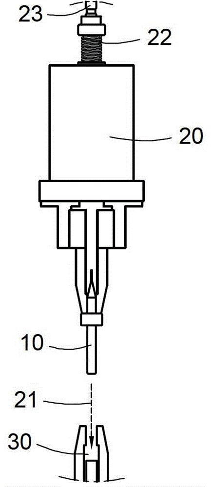
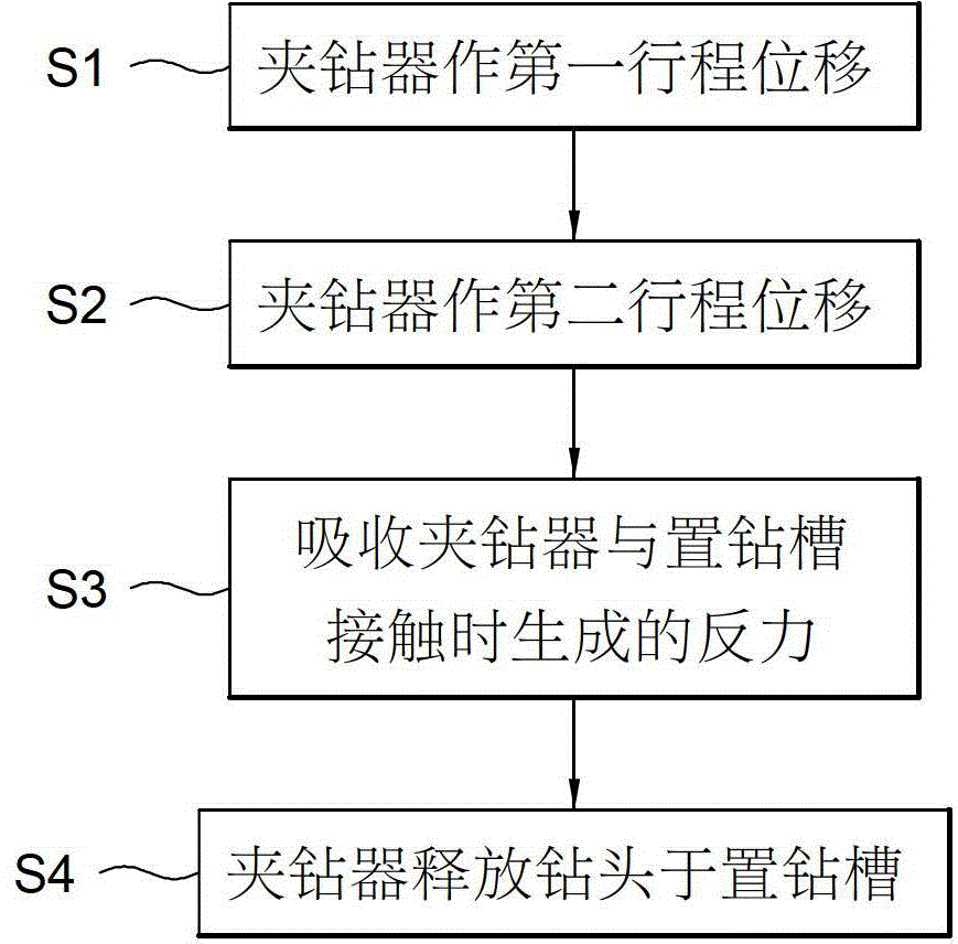
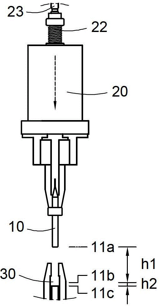
[0041] The purpose of implementing the insertion method, insertion and removal device of the micro-drill of the present invention is to improve the phenomenon of collision with the drill groove by the drill clamp through the two-stage displacement, and to absorb the clamping of the drill clamp to insert the drill bit. The reaction force generated during the process of setting the drill groove increases the service life of the drill clamp and the drill groove. Please refer to figure 1 , figure 2 and Figure 3a to Figure 3e , illustrating an embodiment of the present invention, is to provide a method for inserting a micro-drill. in, figure 1 reveals a schematic configuration diagram of the insertion method of the present invention, figure 2 reveals a flowchart of the insertion method of the present invention, Figure 3a to Figure 3e respectively reveals the execution figure 2 Schematic diagram of the method in action.

[0042] see figure 1 , indicating that a drill cl...


PUM


Abstract

A tiny drill bit insertion method comprises moving a drill clamping device towards the direction of a drill placement groove to perform first stroke displacement and performing second stroke displacement, wherein a tiny drill bit is clamped through the drill clamping device; the tiny drill bit is inserted to be in contact with the drill placement groove through the drill clamping device before the second stroke displacement ends; counter-force is generated to be applied to the drill clamping device when the tiny drill bit is inserted in and is in contact with the drill placement groove; the tiny drill bit is released to be positioned in the drill placement groove after the counter-force is absorbed by the drill clamping device through an elastic element. The invention further comprises a tiny drill bit insertion and taking device required by implementation of the tiny drill bit insertion method.

Description

technical field [0001] The invention relates to the technology of inserting and taking out a micro-drill, in particular to a method for inserting a micro-drill and a device for inserting and taking in and out. Background technique [0002] At present, in the automatic processing tools for detecting and grinding micro-drills, the micro-drills are generally clamped by drill clamps, and the micro-drills are inserted into the drill grooves for testing and grinding. During this process, the pneumatic cylinder is usually used to drive the movement of the drill clamp, so that the micro drill bit can be quickly accepted and inserted into the desired drilling position. In the meantime, in order to enable the fine drill bit to be accurately inserted into the drill groove, the distance that the pneumatic cylinder drives the drill clamp to move toward the drill groove must be deliberately slightly larger than the distance between the drill clamp and the drill groove, and using the The ...

Claims


Application Information

Patent Timeline
Patent Type & Authority Applications(China)
IPC IPC(8): B24B3/24
CPCB24B3/24B24B41/06
Inventor 姚志金
Owner PHOWN ENTERPRISE
Learn More