A three-way solenoid valve

A technology of three-way solenoid valve and spool, applied in multi-way valves, valve details, valve devices, etc., can solve the problem of high cost, achieve the effects of controlling manufacturing costs, improving processing technology, and simple structural layout

Active Publication Date: 2018-01-26
ZHEJIANG SANHUA COMMERCIAL REFRIGERATION CO LTD
View PDF12 Cites 0 Cited by
  • Summary
  • Abstract
  • Description
  • Claims
  • Application Information

AI Technical Summary

Problems solved by technology

In the prior art, in order to ensure a certain service life of the product, the transmission rod 2 is usually selected to use higher strength materials, and the cost is relatively high

Method used


Image

  • A three-way solenoid valve
  • A three-way solenoid valve
  • A three-way solenoid valve

Examples


Embodiment Construction

[0030] The core of the present invention is to provide a three-way solenoid valve, which can effectively improve the processing technology through structural optimization, and at the same time, provide a reliable guarantee for controlling the manufacturing cost of the product. A detailed description will be given below in conjunction with the accompanying drawings of the description.

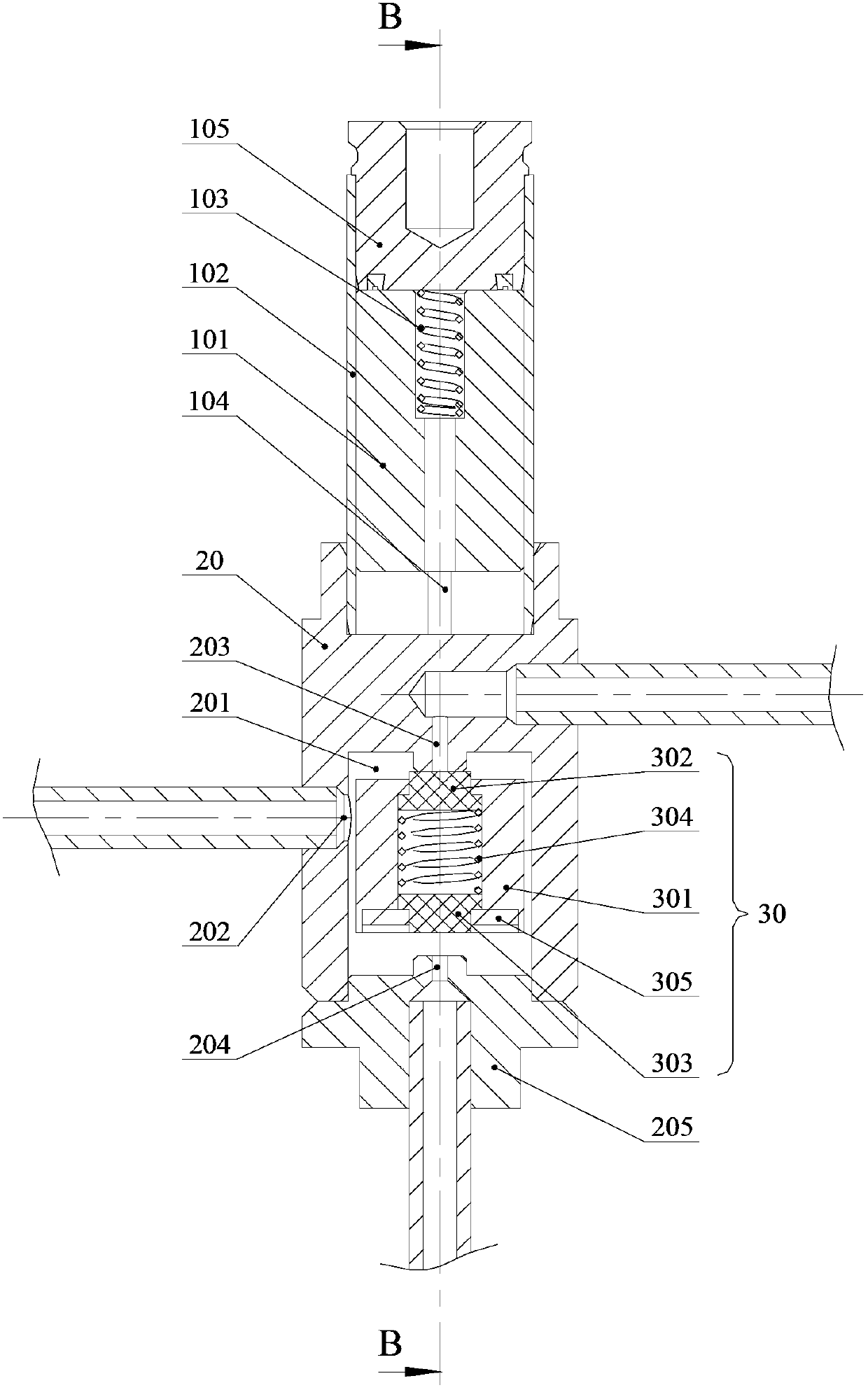
[0031] See image 3 , which shows a schematic diagram of the overall structure of the three-way solenoid valve in this embodiment.

[0032] Such as image 3As shown, the driving part of the three-way solenoid valve is mainly composed of a suitable coil (not shown in the figure) and a core iron 101, the core iron 101 is built in the sleeve part 102 fixedly connected with the valve seat 20, and A second elastic member 103 is arranged between the core iron 101 and the blocking member 105 of the casing 102; specifically, after the coil is energized, an axial force for switching to the second worki...


PUM


Abstract

The invention discloses a three way electromagnetic valve. The three way electromagnetic valve comprises a valve seat and a drive component which outputs axial displacement driving force, wherein the valve seat is provided with an internal valve cavity, and an inlet and two outlets, which are communicated with the internal valve cavity, a valve core component connected with an output piece of the drive component is arranged in the internal valve cavity, and the valve core component can be switched between two work positions under drive of the output piece, and is configured so as to form the work modes that the valve core component blocks a first outlet and the inlet is communicated with a second outlet when the valve core component is located on a first work position, and the valve core component blocks a second outlet and the inlet is communicated with a first outlet when the valve core component is located on a second work position. According to the three way electromagnetic valve, the inlet and the two outlets of refrigerant are all communicated with the same internal valve cavity, and accordingly the problems caused by forming a middle runner between two existing valve cavities are completely avoided, and processing manufacturability of the valve seat is greatly improved. Furthermore, the three way electromagnetic valve is simple in structural arrangement and can effectively control product manufacture cost.

Description

technical field [0001] The invention relates to a valve element technology for a heat exchange system, in particular to a three-way electromagnetic valve. Background technique [0002] As we all know, heating and cooling air-conditioning devices usually have two heat exchangers, so as to realize the heat exchange and conversion in different positions at different time periods; The heat exchanger is switched to the B heat exchanger at time t2, and the refrigerant needs to be controlled to flow through the B heat exchanger, that is, the refrigerant needs to be switched between the two flow channels. [0003] In the prior art, a three-way solenoid valve is mostly used to meet the above-mentioned functional requirements, and the switching of the refrigerant between the two flow channels is controlled by controlling the power on and off of its coil. For details, please refer to figure 1 , which shows a schematic diagram of the overall structure of a three-way solenoid valve. ...

Claims


Application Information

Patent Timeline
Patent Type & Authority Patents(China)
IPC IPC(8): F16K11/044F16K31/06
CPCF16K11/044F16K31/0627
Inventor 不公告发明人
Owner ZHEJIANG SANHUA COMMERCIAL REFRIGERATION CO LTD
Why Eureka
Try Eureka