Flange

A flange and fixed flange technology, applied in the direction of flange connection, pipe/pipe joint/pipe fitting, through components, etc., can solve the problem of time-consuming and laborious, and achieve the effect of small tool requirements

Active Publication Date: 2014-08-27
ZHEJIANG GOOD FITTINGS
View PDF8 Cites 17 Cited by
  • Summary
  • Abstract
  • Description
  • Claims
  • Application Information

AI Technical Summary

Problems solved by technology

[0002] Flanges are parts that are connected to each other between pipes, and are used for connection between pipe ends; there are bolt holes on the flange, and the bolts make the two flanges tightly connected. Flange connection is an important connection method in pipeline construction

Method used


Image

  • Flange
  • Flange
  • Flange

Examples


Embodiment Construction

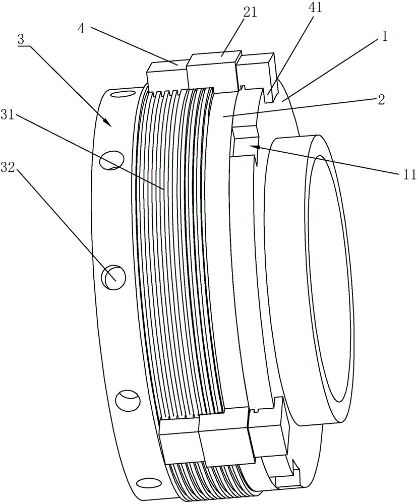
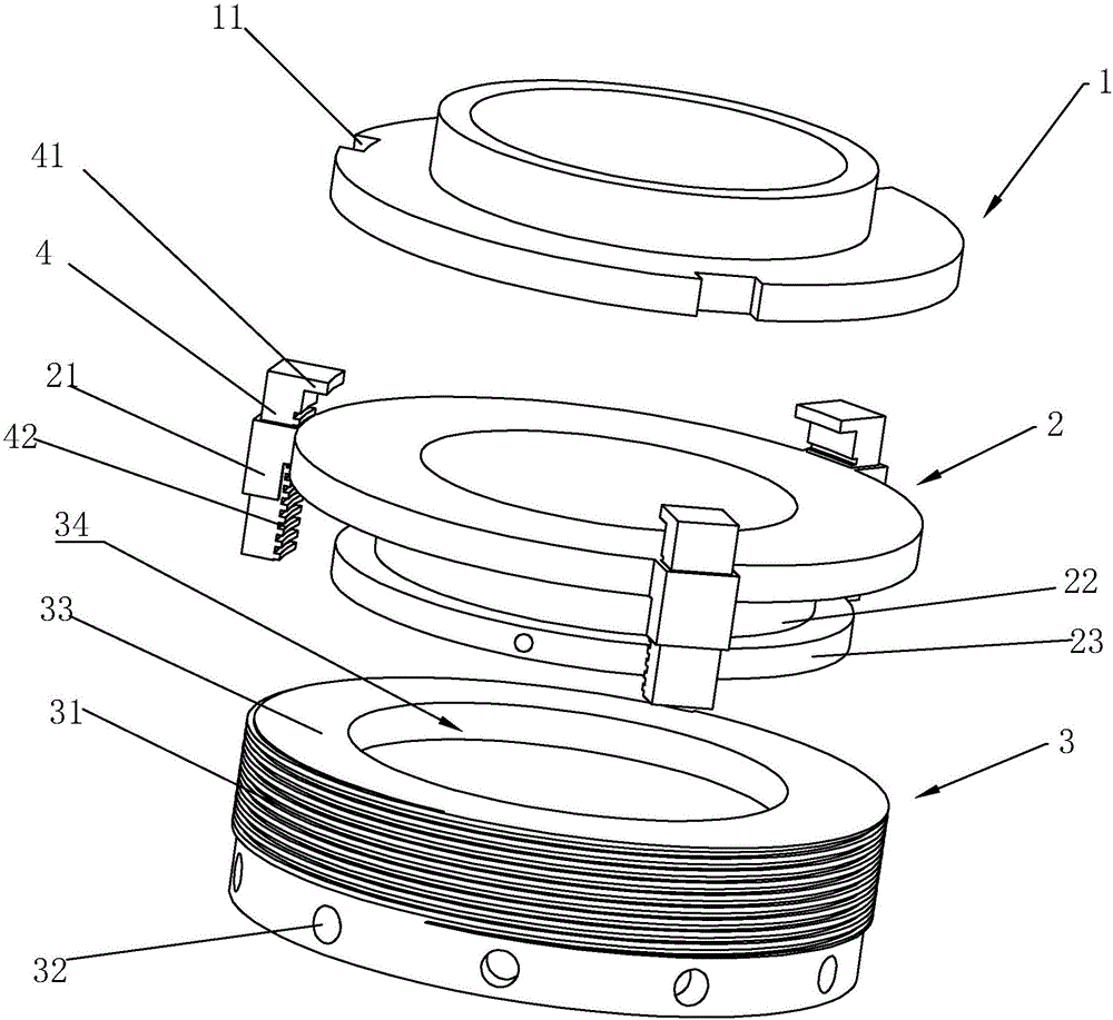
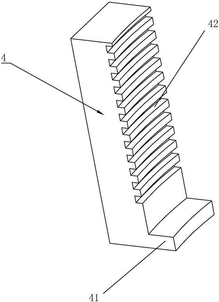
[0025] refer to Figure 1 to Figure 4 The embodiment of the flange of the present invention will be further described.

[0026] A flange, including a fixed flange 2 and a connecting flange 1, a fixing device is provided between the fixed flange 2 and the connecting flange 1, and an axial slide groove 24 is provided on the fixed flange 2, The fixing device includes a claw 4 arranged on the chute 24, the claw 4 is provided with a clamping part for fixing the connection flange 1, and the fixed flange 2 is also provided with a drive claw 4 axis A drive mechanism for moving in the direction, the drive mechanism includes a drive wheel 3 rotating in the circumferential direction, the drive wheel 3 is provided with a guide rail 31 spirally wound around the central axis, and the claw 4 is provided with a guide rail 31 adapted to The guide groove 42 (the driving mechanism can also be replaced by other means, such as hydraulic pressure).

[0027] By adopting the above-mentioned technic...


PUM


Abstract

The invention discloses a flange. The flange comprises a fixation flange and a connection flange. A fixation unit is arranged between the fixation flange and the connection flange, and a plurality of axial sliding grooves are formed in the fixation flange. The fixing unit comprises clamping claws arranged in the sliding grooves, and clamping portions for being fixedly connected with the connection flange are arranged on the clamping claws. A drive mechanism for driving the clamping claws to move axially is arranged on the fixation flange and comprises a drive rotation wheel rotating circumferentially, and guide rails wound spirally around the central axis are arranged on the drive rotation wheel. Guide grooves matched with the guide rails are formed in the clamping claws. The flange is convenient and quick to mount and dismount.

Description

technical field [0001] The present invention relates to a pipe connector, more specifically, it relates to a flange. Background technique [0002] Flanges are parts that are connected to each other between pipes, and are used for connection between pipe ends; there are bolt holes on the flange, and the bolts make the two flanges tightly connected. Flange connection is an important connection method in pipeline construction. Flange The connection is easy to use and can withstand high pressure. In industrial pipelines, flange connections are widely used. However, during the installation or removal of ordinary flanges, bolts need to be installed or removed one by one, which is time-consuming and laborious. Contents of the invention [0003] In view of the deficiencies in the prior art, the purpose of the present invention is to provide a flange that is easy to install and disassemble. [0004] In order to achieve the above object, the present invention provides the following...

Claims


Application Information

Patent Timeline
IPC IPC(8): F16L23/032F16L23/024
CPCF16L23/024F16L23/032
Inventor 杨月洁罗先兵
Owner ZHEJIANG GOOD FITTINGS
Why Eureka
Try Eureka