An oil-immersed three-phase transformer

A technology of three-phase transformers and transformers, applied in the field of transformers, can solve problems such as low heat dissipation efficiency, transformer damage, transformers entering dust, etc., and achieve the effect of simple structure, ensuring normal operation, and preventing dust from entering

Active Publication Date: 2022-04-15
YANTAI MUPING POWER SUPPLY CO OF STATE GRID SHANDONG ELECTRIC POWER CO
View PDF0 Cites 2 Cited by
  • Summary
  • Abstract
  • Description
  • Claims
  • Application Information

AI Technical Summary

Problems solved by technology

[0004] The purpose of the present invention is to solve the problem of using heat sinks to dissipate heat in the prior art, but heat sinks are usually arranged inside and emit heat through vent holes, but such heat dissipation efficiency is not high, and the vent holes are all Open, it is easy to cause the transformer to enter dust and cause damage to the transformer, and an oil-immersed three-phase transformer is proposed

Method used


Image

  • An oil-immersed three-phase transformer
  • An oil-immersed three-phase transformer
  • An oil-immersed three-phase transformer

Examples


Embodiment 1

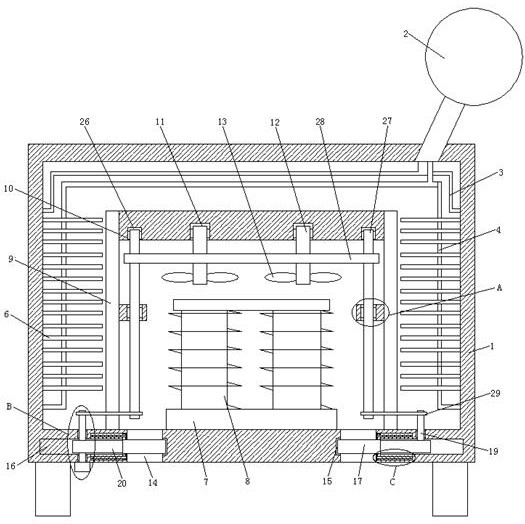
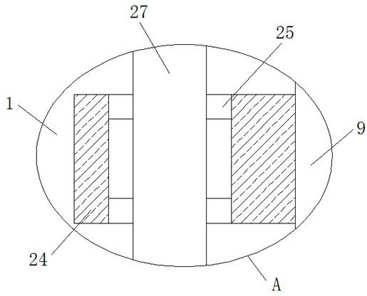
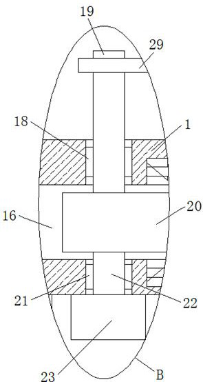
[0027] refer to Figure 1-5 , an oil-immersed three-phase transformer, comprising a transformer casing 1 set in a hollow structure, an oil tank 2 is fixedly installed on the top of the transformer casing 1, an oil inlet pipe 3 and an oil outlet pipe 4 are fixedly installed inside the transformer casing 1, and the oil inlet pipe 3 and the oil outlet pipe 4 are fixedly installed inside the transformer casing 1 The oil outlet pipes 4 are all connected with the oil tank 2, and a plurality of heat conduction pipes 6 are arranged on the outside of the oil outlet pipes 4. An embedded plate 7 is fixedly installed on the inner wall of the bottom of the transformer shell 1, and a transformer main body 8 is fixedly installed on the top of the embedded plate 7. A support column 9 is fixedly installed on the inner wall of the bottom of the housing 1, and the side where the two support columns 9 are close to each other is fixedly installed with the same support plate 10 above the transformer...

Embodiment 2

[0038] refer to Figure 1-5 , an oil-immersed three-phase transformer, comprising a transformer casing 1 set as a hollow structure, the top of the transformer casing 1 is fixedly connected with an oil tank 2 through bolts, and the inside of the transformer casing 1 is fixedly connected with an oil inlet pipe 3 and an oil outlet pipe 4, and Both the oil inlet pipe 3 and the oil outlet pipe 4 are connected with the oil tank 2, and a plurality of heat conduction pipes 6 are arranged on the outside of the oil outlet pipe 4. The bottom inner wall of the transformer shell 1 is fixedly connected with an embedded plate 7 by bolts, and the top of the embedded plate 7 is connected by bolts. The transformer main body 8 is fixedly connected, and the bottom inner wall of the transformer housing 1 is fixedly connected with a support column 9 by bolts, and the side of the two support columns 9 close to each other is fixedly connected with the same support plate 10 above the transformer main b...


PUM


Abstract

The present invention belongs to the field of transformers, especially an oil-immersed three-phase transformer. For the existing cooling fins, the cooling fins are usually installed inside to dissipate heat through ventilation holes, but such The heat dissipation efficiency is not high, and the ventilation holes are all open, which will easily lead to dust entering the transformer and causing damage to the transformer. The following solution is proposed, which includes a transformer casing with a hollow structure, and an oil tank is fixedly installed on the top of the transformer casing , The oil inlet pipe and the oil outlet pipe are fixedly installed in the transformer shell. The present invention is simple in structure, easy to operate, can effectively dissipate the heat generated by the main body of the transformer during the working process, and can effectively dissipate heat when the external temperature is relatively high, so as to ensure the normal operation of the main body of the transformer. At the same time, when the heat dissipation is completed, it can The heat dissipation port is sealed to prevent dust from entering, so people's needs are met.

Description

technical field [0001] The invention relates to the technical field of transformers, in particular to an oil-immersed three-phase transformer. Background technique [0002] The three-phase transformer is a complete set of voltage transformation equipment, which can be used for terminal power supply and ring network power supply. The conversion is very convenient and ensures the reliability and flexibility of power supply. However, the transformer will generate a lot of heat during operation. Mainly by setting air passages or oil passages in the body, the heat is taken away by the circulating flow of gas or oil to dissipate heat. Its structure is complex, manufacturing and maintenance is difficult, and it is highly specific to the type of transformer and does not have universal applicability; [0003] Traditionally, heat sinks are also used to dissipate heat, but the heat sinks are usually installed inside to dissipate the heat through the ventilation holes, but the heat diss...

Claims


Application Information

Patent Timeline
Patent Type & Authority Patents(China)
IPC IPC(8): H01F27/08H01F27/12H01F27/02
CPCH01F27/08H01F27/12H01F27/022H01F27/025
Inventor 王蓬军曲健矫炜秦德军刘宏江王新科张海峰孙冰王秀娟
Owner YANTAI MUPING POWER SUPPLY CO OF STATE GRID SHANDONG ELECTRIC POWER CO
Why Eureka
Try Eureka